This is my DIY Sump. It is installed under my 150 gal reef tank in a cabinet stand.
This design has been in use for over 3 years now, and there isn’t really anything I would change. It is about as simple as it can be.
I recently removed the sump from the system to clean it, and took some photos.
Layout
The sump is made from a new 40 breeder aquarium. It is an Aqueon brand that I bought from Petco as part of their “$1 per gallon” sale.
Advantages
Large Return Section – This is one of the nicest things to have in a sump design. The return pump can be turned off and the return chamber will hold all the water that drains from the overflow box and display. The skimmer will not overflow due to the water level raising past it’s limit. So I never have to worry about turning off the skimmer for any reason during maintenance.
Minimal Baffles – there is only a 2″ wide space in the middle that is lost to having a bubble trap. Many sumps lose much of their available real estate to having too many baffles.
Disadvantages
No weir on skimmer section – This means the water won’t be surface skimmed, and might start to accumulate scum. This was fixed with the addition of a pipe at the end of the post.
Turnover Ratings
My Mag 7 return pump pushes around 550 GPH with my 6′ of head height. The sump runs totally silent and has no sound from trickling or splashing. If you have a higher turnover rate, then noise will be heard first around the filter sock area. This is due to the narrow 6″ weir in that area. This design could run up to about 900 GPH without too much noise, just not totally silent.
Materials
The baffles are all 1/4” glass taken from an old aquarium I dismantled. The filter sock tray is made from 1/2″ HDPE plastic (more info below).
Building your own version
One thing to note – this is a general guide when it comes to measurements. While the height of each panel can be copied directly, the width may change in your case. You will have to get your own tank’s exact measurements, and make any adjustments necessary. This is due to the fact that aquariums are made by hand, and every tank may be slightly different.
Check out the Reef Tank Sump DIY Guide for help with construction. It shows how to properly measure and cut panels. It also shows how to set up and then silicone them into place.
Baffle Heights
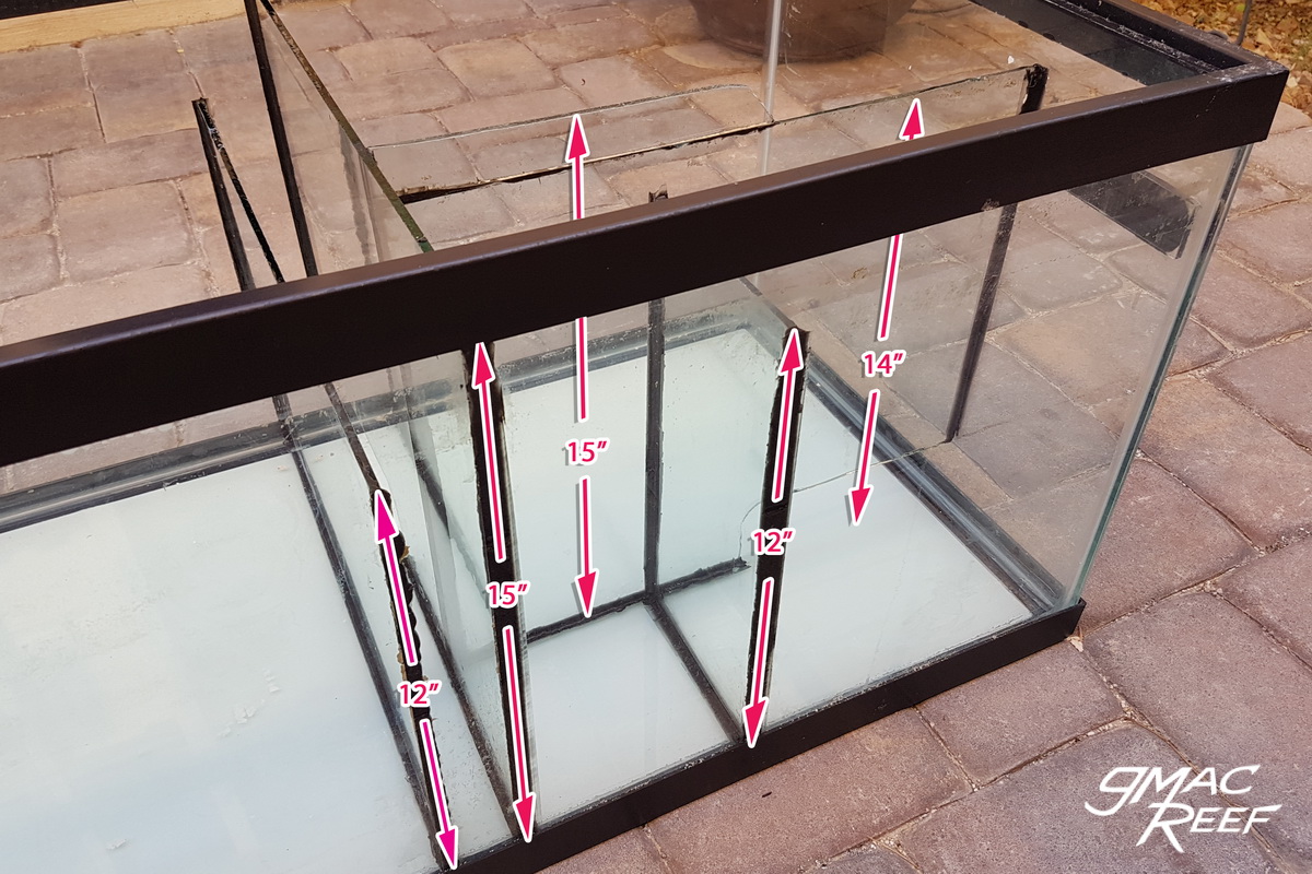
The 12” baffle (the last one in the series) sets the height of the skimmer chamber’s water level.
The sump holds as much water as possible during normal operation (about 25 gallons), while still allowing for drainage when the return pump is shut off.
If you are trying to design your own sump, and figure out what size and height to make sump baffles, look to the Sump Design page.
Notches
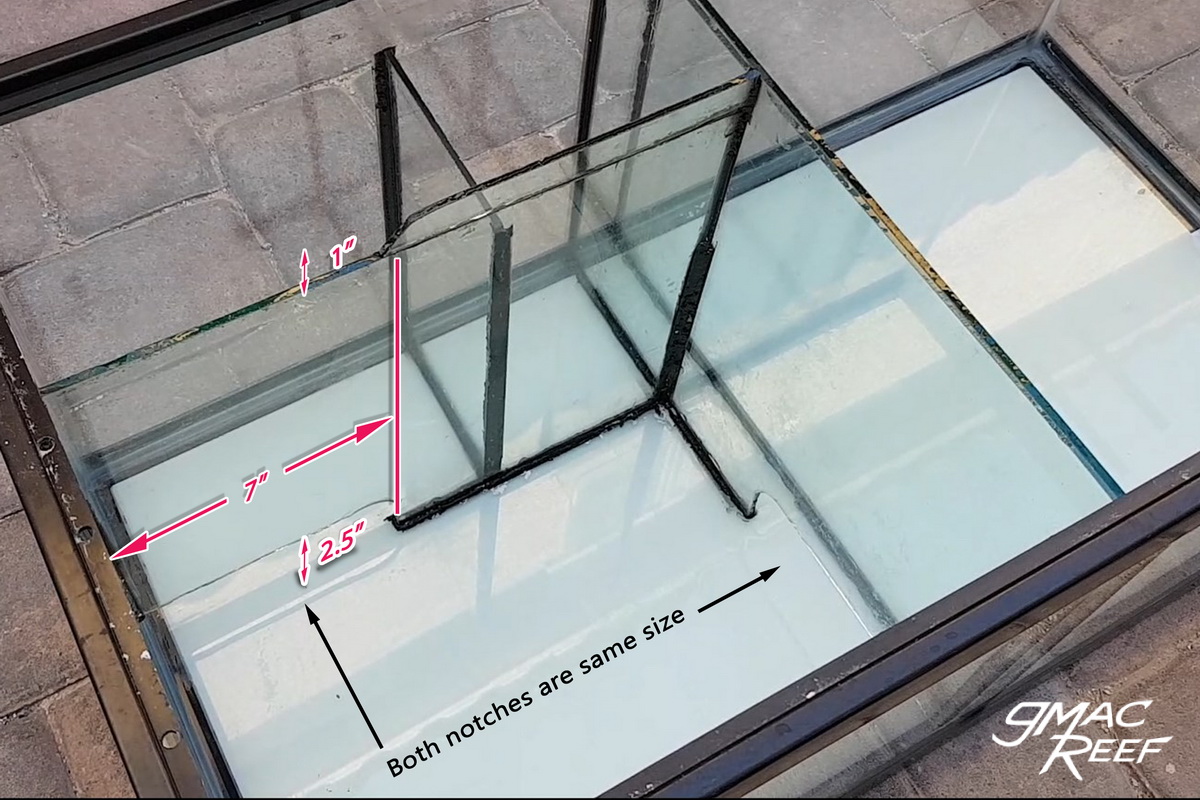
The notches cut in the bottom corners of the baffles allow water to pass under, similar to a raised baffle.
These seem to work well for this tank at the size I made them, however if made slightly smaller they would still work fine.
To see how I cut them, go to the Sump Baffles Construction page.
Bubble Trap
This sump has an under-over series of 2 baffles. This is sufficient at getting rid of the small amount of bubbles that the skimmer occasionally produces (such as when it is cleaned – but only for a day or so). While often seen, 3-Baffle bubble traps are unnecessary and just take up a lot of room. Long weirs and slow flow work best.
Filter Sock Tray
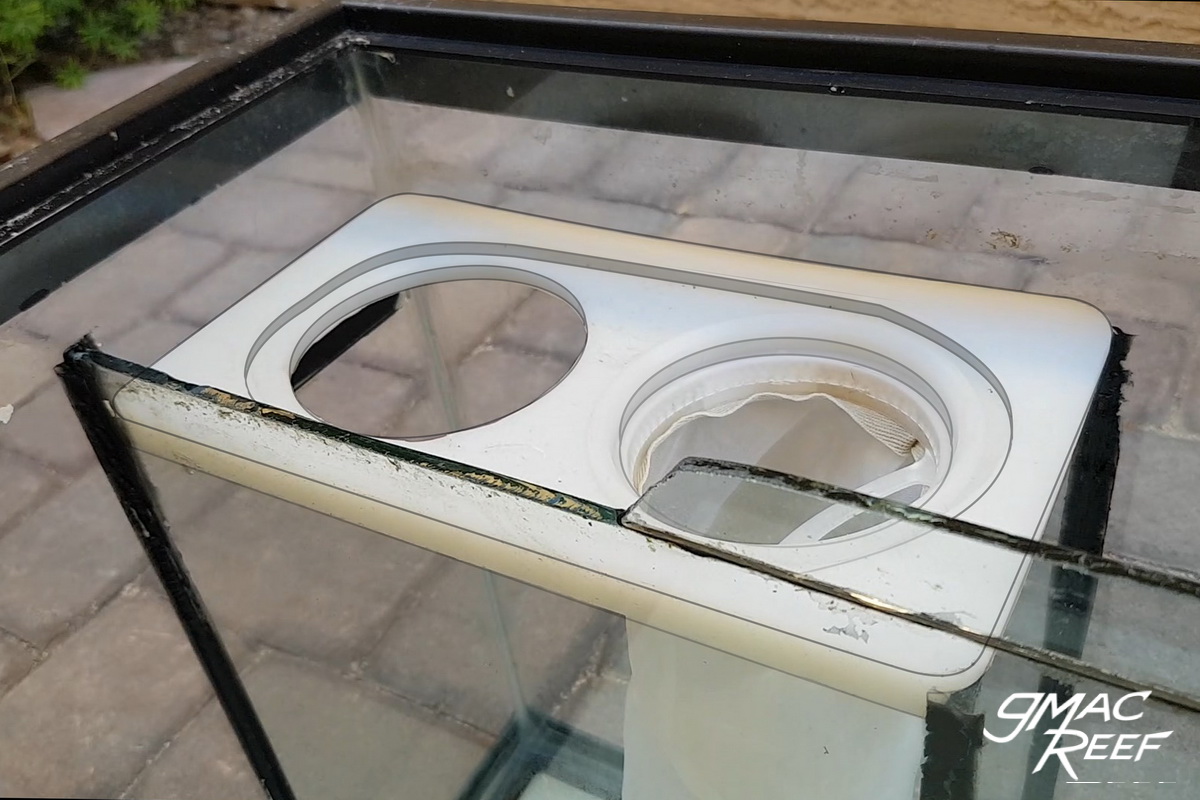
There is a filter sock tray that holds 2 X 4″ filter socks (mine are 200 micron mesh type). The tray is made with 1/2″ HDPE plastic (aka Starboard).
The tray was first cut on the table saw to size, then a router was used to create the rabbet notches on each end. You could also just do a few passes with the table saw to remove the material.
I also used my router to remove some material so the water flows down into the socks better without getting hung up on the “lip” of the socks. This isn’t totally necessary, but it does work better to keep it quiet.
 In the the original photo it was difficult to see the shape – I have traced over the edges in Photoshop to show the profile.
With this design, the tray needs to fit tightly. It should not allow any water to bypass the socks.
If the socks get too dirty, water will just flow over the wall to the next chamber.
Whenever you are making a piece like this, it is always a good idea to make a test piece first. That way you figure out your dimensions before you cut your “good” material.
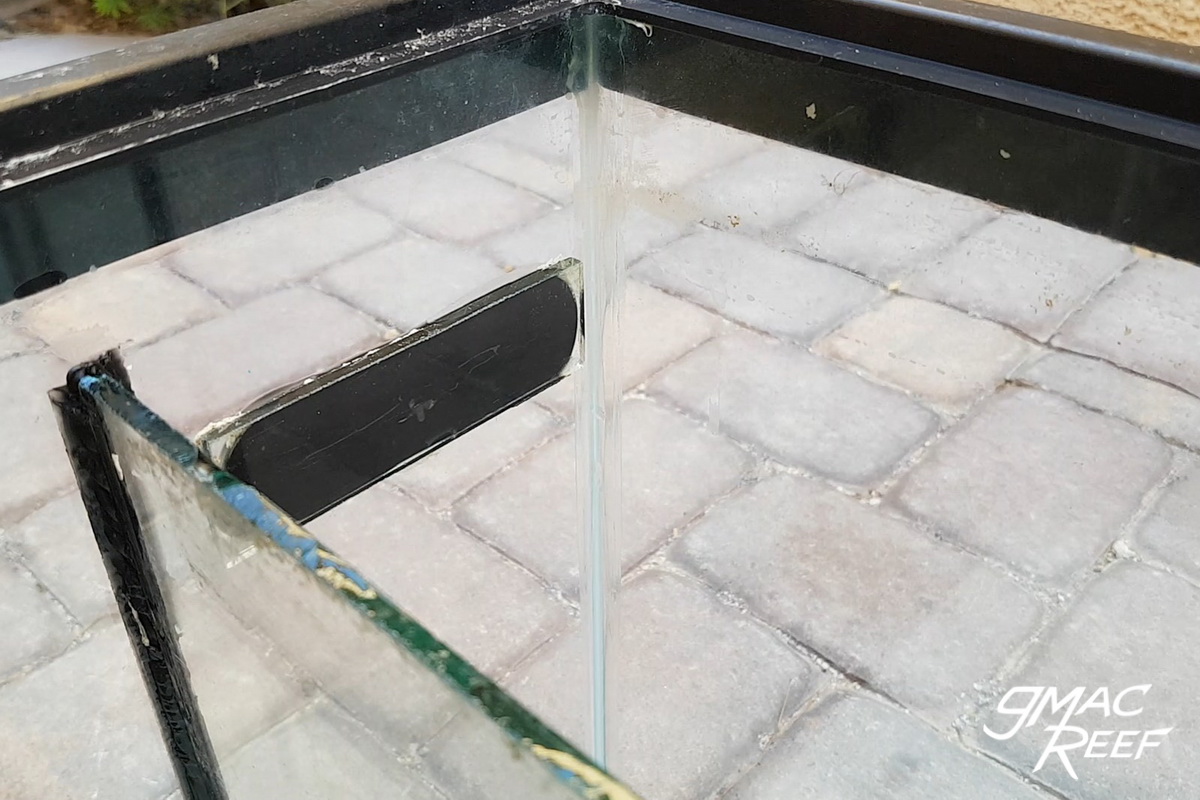 This piece of glass siliconed to the tank simply gives the tray a place to rest on. It’s dimensions don’t matter much.
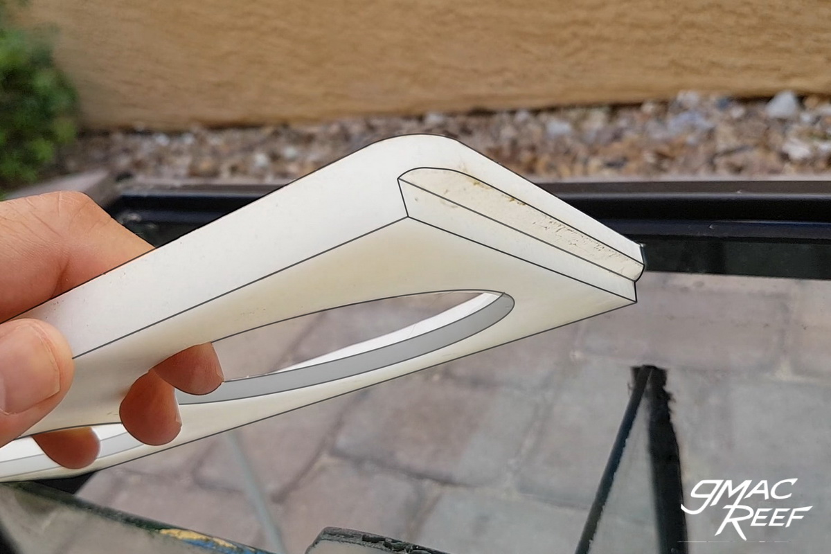 Again, the shape is a little hard to see so I have traced over the image to better show the rabbet on the front edge.
The holes were first cut with a hole saw drill attachment. I chose the bit that made a hole slightly smaller than what I needed. I then used my handheld router with a straight bit to inch up the size of each hole, a little at a time. I had a sock on hand to test fit as I went along. This made for a snug fit for the socks so they can’t float up.
 The notch on the panel shown allows for the chamber to overflow into the skimmer chamber if the socks clog up.
 The sump placed back in the cabinet and filled up. Left to right: Skimmer, Skimmate Container, Heater, ATO sensor, Return Pump, and a Powerhead in the right corner.
Modification to First Chamber
One caveat to only having the baffles in an “under-over” setup is having no weir. This means it won’t surface skim from the first chamber where the skimmer sits. This wasn’t a big deal for the most part because I added a power head to that chamber. This helped reduce surface scum.
After I added a Nitrate reactor to the sump, I was getting a bit more slime and bacteria buildup in the first chamber.
I had thought about adding another baffle to act as a weir. This would have worked well, but I would have lost room in that chamber. It is already quite full with the skimmer and reactor in there. Draining the sump for a week didn’t seem that attractive either.
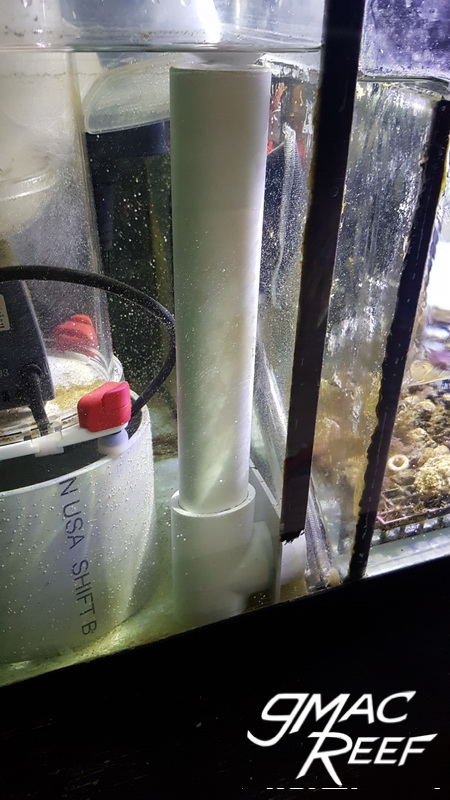
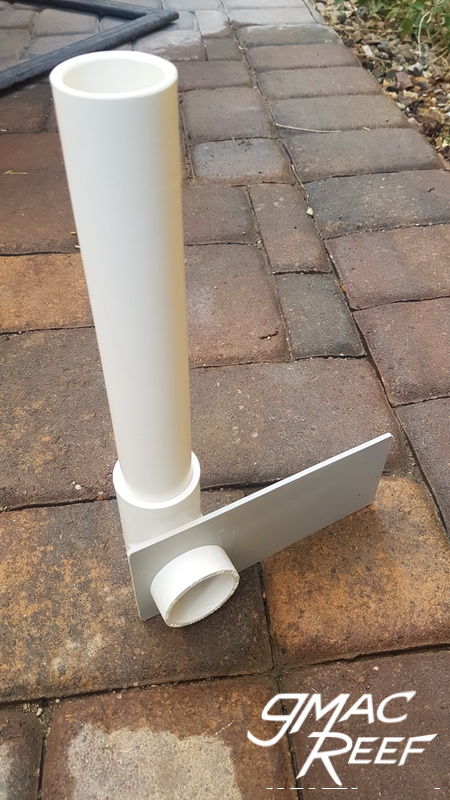
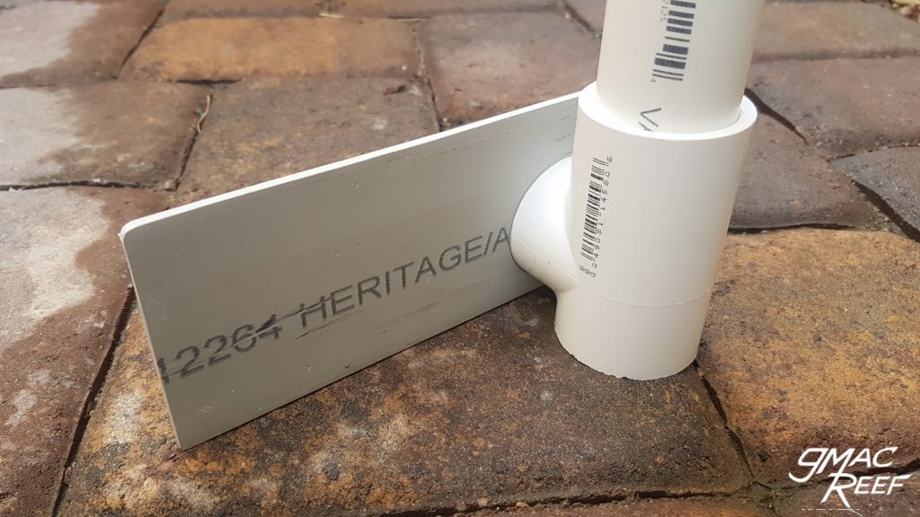
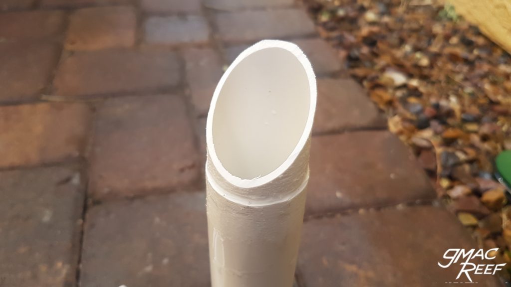
This surface skimming pipe was the solution. It uses a similar concept to an older protein skimmer design with the use of the wedge pipe. This allows you to adjust the amount of water passing through.
It’s a simple design with 3 parts:
- A piece of flattened PVC to cover the existing opening in the baffle.
- a piece of 1.5″ PVC pipe cut at an angle. It was sanded enough to fit in the Tee fitting, with enough clearance to turn freely.
- a Tee fitting. trimmed on the bottom to form a base with the bottom of the plate
The plate covering the opening doesn’t create a perfect seal. A small amount of water passes around the plate. This is the reason it works.
If it was a perfect seal with a single pipe, then it would act as an open drain. This means it would constantly trip into siphon mode, and create noise.
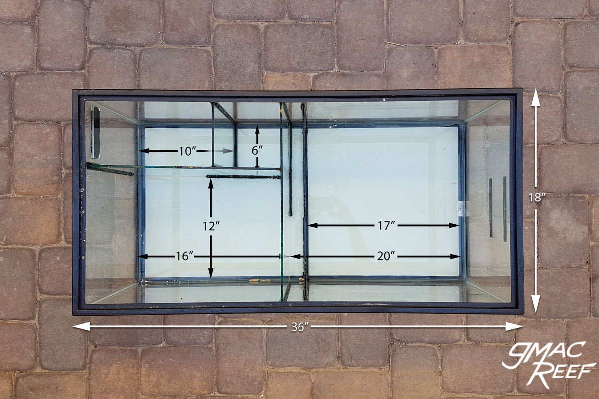

I am just curious, as I am starting to get into my saltwater aquarium hobby and want to upgrade my current setup to incorporate a sump. What was the purpose of the 6 ” x 6 ” area you have next to your filter sock area? I am just trying to learn and comprehend the dynamics of your system. Absolutely love all your posts on this site! I have learned a ton and it has definitely been the most valuable site for me so far in my research. Thank you for putting the time into this!
That is where the drains dump into. I have heard of some sump makers calling this kind of chamber a “crash-box”.
All the drain lines dump into this chamber, then water flows up and over the filter sock tray, and down through the socks.
Designing this way allows you to easily remove and replace filter socks which typically must be done every few days.
The alternative to this method is putting the socks directly under the drain lines. This can make it harder to change them.
The reason it is 6″ x 6″ is so it’ big enough to accommodate all the drain lines. On my 150gal with a Bean setup, I have 3 pipes. A single 1.5″ dry emergency line, and 1″ open channel line and 1″ main siphon line.
Thanks for the comment – glad the site is helpful.
Thanks for the great info! I’m wondering how you plan your sump for noise, particularly how you know the acceptable flow rates for a given width/height of weir for silent operation? Thanks!
Using the turnover rate of the system and the width of a weir, you can calculate height. This is the thickness of the sheet of water passing over. From this, you could measure how much noise is generated from falling water. Calculations are not really necessary though.
The best advice would be to use a wide tank as a sump if you are looking for silence. A wide tank will mean longer weirs are possible. This will mean quiet operation and less bubbles.
Something like a 40 breeder is good because it is 18″ wide. An 18″ wide weir runs much quieter compared to a 12″ one with the same rate of flow.
Thanks! I have an 18″ wide sump, so I should be okay for the main weirs. Your design uses a 6″ wide section before the filter socks, I wonder how you know that’s wide enough, is it just from experimentation?
I really appreciate the info you have about noise, this is one area that’s talked about a lot on the internet, but never with any detail, so I really like that you discuss it on your site.
Thanks
In regards to the section from the crash box to the sock tray:
I knew having a 6″ wide channel for the water to flow through was going to be enough. With my 500GPH of flow, the height of the weir (sheet of water flowing) is about 1/2″ high.
This is the only part of the sump that makes any noise at all. You have to pretty much stick your head in the cabinet to hear it.
If you want to use this design on a system with a higher turnover rate, that section would work best if it were a bit wider. I would modify the design to make it 8″ wide or so.
If you build a sump using a similar design, please share a picture!
Great articles! I designed and built a sump from an old 29 gallon tank that fits under my 65 gallon corner flow planted freshwater tank. I used a U-shaped flow. A few tweaks hear and there, but I am now a sump true believer. I am now planning a sump for my 75 gallon single-corner flow. I want to go with a Bean set-up and I will be using an old 110 gallon tank for the sump, so plenty of room. (It will eventually serve a new 300 gallon tank behind my bar, so I’m not quite as crazy as it sounds.) So … two questions =
1) what is the purpose of the powerhead?
2) have you ever tried one of those roller gizmos instead of filter socks?
The powerhead has no purpose to the sump design. In my case it It just provides more flow to my frag racks in that chamber.
As for #2 — I have not tried a rollermat or similar machine yet, but I’d like to. Water clarity and reduction of nutrients are the main reasons. Not having to change filter socks would be nice too.
As these units have only been out a few years, I think they are still working out some details on the design. I think it comes down to an what is an acceptable amount of roll material and cost for the average person. I have heard of a few people putting them on a timer to limit the amount of filter material usage.
Thanks for the great efforts. Really helpful
I am struggling with what heights and how many baffles I would need to achieve the below
Left to right
1- Section 1 50*40*40cm were overflow pipes will go down in this section will be fuge to support triton method. Planned water height in this section is 40cm
2- Section 2 30*40*30cm will host media reactors and maybe frag racks and the skimmer pump will b located here. Planned water height 30cm
3- Section 3 30*40*20cm where return pump and skimmer will be located and skimmer water outlet will go over to section 2 (might move skimmer to section 2) Planned water height is 20cm
I am afraid with this design the splashing noise of waterfall from baffles will be loud and was wondering what height and how many Over or Under baffles would be required to silence the water flow between the three sections