Reef Aquarium Sumps are something that can be very simple and easy to set up if you know a few things about what you are trying to do.
A big reason why sumps are confusing to beginners is that a lot of people make them way more complicated than they need to be. They see all kinds of pipes going all over the place and think they must be hard to build.
Depending on the stand or cabinet you are using, it can be a hassle to remove or change your sump setup. It is worth putting some thought into how you are going to use it and what it needs to do.
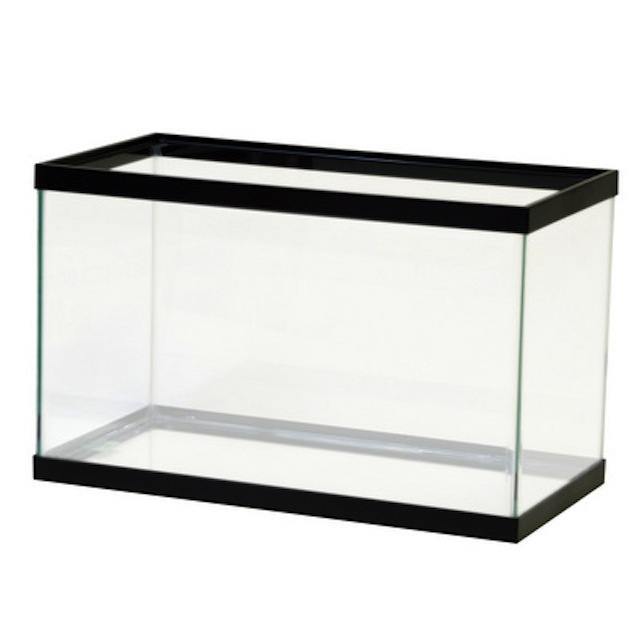
Sumps are simple, and you can turn a $20 Craigslist tank into one that functions just as well as $300 commercial models. This article will go over what I think is the simplest method to set up a sump in a bare tank, with all the reasons behind the design.
What are the main benefits of running a sump?
- act as a buffer-zone where water moves to be filtered mechanically and chemically
- slowly process water in such a way that promotes stability of the water and avoids spikes in water chemistry and temperature
- let you run equipment out of view, so you can have a clutter-free display
- contain any leaks from equipment or reactors from reaching the cabinet or floor
Hands-on guide also available
If you have all the design and baffle heights worked out and just want to get to building your sump out of a spare tank, go to this page: Reef Tank Sump DIY Glass Baffles Guide
What we’re trying to do here
- catch the water from the overflow drain outlet
- deliver water to the equipment that processes it
- remove any microbubbles that may have been generated by the equipment
- return the water to the aquarium as quietly as possible
But we also want to make sure we:
- have enough room to deal with back-siphoned water when the return pump turns off
- have fail-safes in place where possible to prevent floods
- cooperate with the Herbie, Bean or “siphon-based” overflow designs
Size Considerations
Most of the time, you’ll want to have as big of a sump as you can fit in the area.
Having a larger sump just makes a few things easier and less complicated. A bit of extra room to work with means being able to run just about any equipment you want. It’s nice to have some space available for extra live rock, reactors, and those sort of things.
The 3-chamber design shown in this article will work for the majority of larger sumps. If a small tank must be used – say 10-20 gallons – then you will probably have to alter the design and not use the center chamber. With a small sump, a 2-chamber design will allow the return pump chamber to hold enough water.
How much turnover should we have?
There are not many benefits to running high rates of turnover through your sump, other than having more water pass through mechanical filtration. Each individual piece of equipment processes water at it’s own rate, but most can process a very small amount at a time. For that reason I generally recommend a rate around 5X-7X of the display volume per hour. More on turnover rate here: What is the right turnover rate for a reef tank?
1st Stage – Where water from the overflow drains into the sump
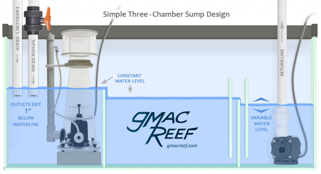
The first chamber will have the highest water level and then cascade down to the other ones. For the first divider, you want the water to pass over a weir of some kind.
The reason for having water go over a wier is to maintain a consistent water level in the first chamber.
A consistent water level is something we need for the skimmer to work problem-free, and it’s also helpful if you have a siphon-based overflow. In order for the siphon to start, the outlet of the pipe must be submerged, but only by about 1″ (3cm) below the water surface. A siphon can’t start correctly otherwise.
Designing for your Skimmer
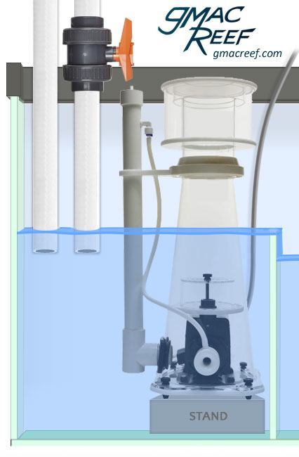
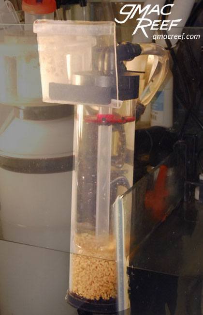
Most new skimmers available are non-recirculating models that operate in-sump. They usually have a recommended water height from the manufacturer they are designed to work at. This is usually at between 7-12 inches of water…
When a skimmer is dialed-in and properly adjusted, it’s pretty touchy. If the surrounding water level in the chamber rises, it reacts by overflowing the collection cup and skimmate collector. Not fun to clean up.
If you design this chamber to have all the water flow to the next one by passing over a weir, this won’t happen.
So if you are trying to figure out how tall to make the divider between this first chamber and the next, you may want to choose something close to 12″. You can boost a skimmer up to the right height with a DIY stand of some kind, but you can’t lower it if it’s already too high…
Having ample water depth in the first chamber gives you options. It allows you to change or upgrade your skimmer, just by adjusting the height of the platform.
Dealing with Back-Siphoning
When the return pump is turned off, gravity will cause the water currently being pumped up to the tank to fall back down. This means the sump will start filling up a bit.
The water comes from a few places. First, the water in the display tank will flow back through the return. Second, the water inside the overflow will drain. Lastly, some water from inside the pipes will drain down.
When added together, this can add up to several gallons of water flowing down to the sump.
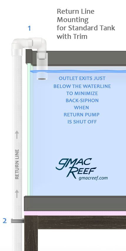
There are ways to reduce this amount of water by correctly designing your Return Line and Overflow System, but no matter what – there will always be some back-siphoning of water.
This is why it’s nice to have a bit of elbow room when it comes to your sump’s capacity.
Ways to Minimize Drainage
Before we even get to planning out the layout of the sump, it is beneficial to reduce the amount of water that back-siphons and drains into it.
This is done by:
- Return line outlet only submerged the minimum amount below the surface of the display tank.
- Correct height of standpipes in overflow box – water will drain to level of lowest inlet in the box when the return pump shuts off.
Stage 2 – Housing Equipment (Optional)
The middle chamber of the design can have many uses. This can be an area for reactors, heaters, or anything else. Hanging lighting over the area for a frag rack or refugium area is also common. You will most likely want a constant water level in this chamber too. This avoids the risk of having pumps or heaters running dry from a low water level.
Return Pump Chamber – Where the water level fluctuates
Your return pump goes in the last stage of your sump, how ever many chambers that ends up being. The water level here will lower as water evaporates, and raise when you top off the system with fresh water. So some people will mark the glass to show what the water level is supposed to be at when the system is topped off.
A piece of masking tape to indicate the high water mark can be helpful. Make sure that when you mark this point, the return pump has been shut off and all water has collected in the sump from the overflow and return line… That is the true high point.
Making sure the sump doesn’t overflow
By designing the sump to have water flow over a series of weirs, we control where the the water level will change. As it falls from chamber to chamber, it will collect at the end. This last chamber’s water level will vary based on evaporation or top-offs.
So this means all the other chambers up the river (the ones where water passes over a weir) will remain consistent.
A cause of frustration among first-time sump builders is overfilling. It is often not discovered until the plumbing is done and the return pump is turned on, then turned off.
It can be tempting to make your return pump chamber very small, because that is probably the only piece of equipment that is going in there. Might as well make lots of room for the other chambers, right?
This can have unintended consequences, which I’ll explain.
When the return pump shuts off, gravity takes over. Water will start to drain from the overflow box, display tank, and inside the plumbing. All this water collects in the return pump chamber. If it can’t handle the volume, the water will fill the other chambers upriver. This can result in the skimmer overflowing or in the worst case the whole sump.
Overfilling when the return pump is shut off is the result of a simple problem — The chamber where it resides is too small.
Contrary to many sumps you have seen, the return pump chamber will often be the largest chamber in the sump.
The good news is that overfilling due to back-siphoning is easy to avoid. By calculating the return pump chamber volume beforehand, we can estimate how big it needs to be in the planning stage.
Determining Return Pump Chamber Size
First, we know that the return pump rests on the bottom of the sump.
It’s meant to be fully submerged, so we need at least the height of the pump itself as a minimum water level.
As the water evaporates from the system, the water level falls in this chamber. So at a certain point, the water level will get low enough that air starts to get sucked in.
If this happens, a loud slurping sound will be heard.
The typical pump won’t slurp air unless the water level is very near the inlet. So you need 2-3″ of water above it to prevent this from happening.
Figuring out how much water needs to be in there to keep from sucking in air gives you a baseline. This baseline will be where you can start measuring the volume of the extra capacity needed for drainage. This baseline water level will be also be close to the normal operating level of the chamber — while the return pump is on.
For example, in this case we will say that 6″ of water is the minimum water level that a return pump can operate without it starting to suck in air.
Above the 6″ mark will be the base of our needed “extra capacity.”
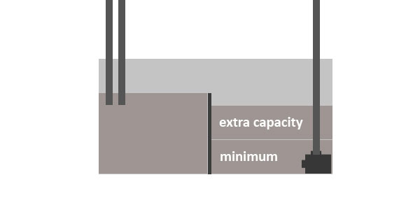
Calculating Extra Capacity or for when the return pump is shut off and the system comes to rest
There will be a few gallons of water that drains down from these sources:
- Overflow box (drains to lowest inlet or standpipe)
- Display tank – the amount of water between the height of bottom of overflow weir and the height of the lowest point of the return outlet (usually only about 1/2″ of depth if you design it right)
- Inside the pipes (not much water unless using long runs of pipe)
So by adding these three sources together, we calculate the extra capacity needed when the pump shuts off. In the case of the overflow box and display water, the volume is easily calculated with L X W X H.
When the extra capacity is added to the minimum, we find out the total required capacity of the return pump chamber.
ATO’s
Even if you decide to forgo these calculations and just use a check valve, there is another issue with creating a return pump chamber that’s too tiny. There will be a lot of swing in the water level height. This means that the water level in that chamber will rapidly go down as water evaporates from the system, and rapidly rise when the return pump is shut off and water empties from the pipes…
So why does this matter?
Well if you are using an ATO (and you should for many reasons), then you will want it to top up the system a few times per day, but no more than that. If the chamber’s volume is too small, then the ATO’s sensor will trip constantly — possibly shortening the unit or pump’s life from overuse.
For this reason you might want to make your return pump chamber larger, just to avoid this excessive swing in water level height.
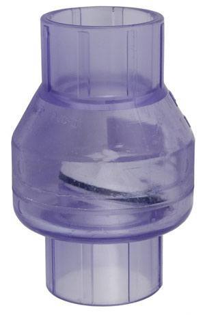 Some people just use a check valve on the return line to prevent most back siphoning. If you want to reduce risk that your system will overfill, then you should not use a check valve because of their eventual potential for failure. More info on this page: Return line Plumbing
Measuring Volume:
(Measured in Inches)
(L X W X H) / 231 = Gallons
Teeing Off the flow of the Return
Some people will use their return pump to also feed the refugium or one or more reactors. This means they they Tee off the return line and direct some of the flow over to that equipment.
A downside to Teeing off the return to feed either a skimmer or a reactor is that it will affect the return rate up to the display.
The return rate affects the overflow. If you have a siphon-based overflow like a Herbie or Bean Overflow, then variations in flow will mean re-adjusting the valve. This can be annoying to have to do all the time.
These variations in small amounts of flow is one reason why the Bean Overflow design has an advantage over a Herbie design. The Bean has the ability to take on variances in the rate of flow through it’s open channel, where the Herbie would need to have the valve adjusted.
So if you’ve got a siphon-based overflow, the system works best if the return pump’s only job is to push water up to the display. The flow may be Tee’d off to provide flow to something that provides consistent pressure such as a refugium chamber, however diverting flow to a manifold to power media reactors generally doesn’t work well with a siphon based drain. This is personal preference because most people don’t want to deal with frequent adjustments.
Sump Construction
The dividers of a sump are called Baffles — vertical panels siliconed in place. The configuration of the baffles determines how the water flows from chamber to chamber.
In a glass sump, you should use glass baffles. Using silicone to affix acrylic panels to glass doesn’t work well in general as it will never create the same strong permanent bond as silicone to glass.
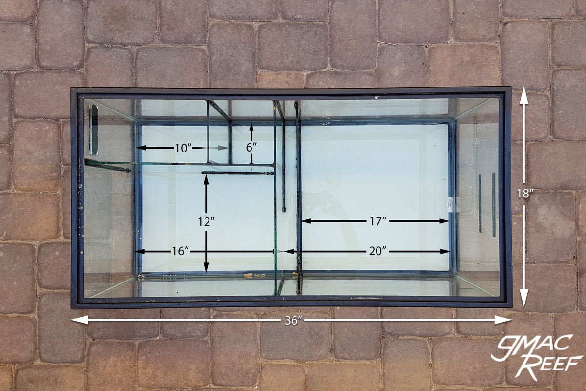
Building a DIY Glass Sump
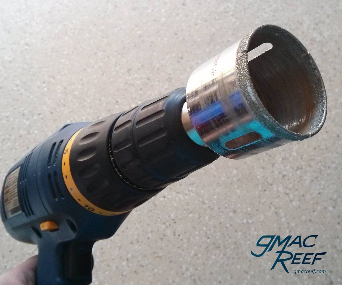
All of the hands-on aspects of building your own sump out of a glass tank are covered in this new post. What glass to use, how to cut it, and how to silicone it into place.
Dealing with Microbubbles
Tiny bubbles in the water are called “Microbubbles” and will blow around in the current of the water column, until eventually bursting at the surface. While they are harmless, they can detract from the crystal-clear look of the water. Common sources can be skimmers and overflow pipes, or anywhere water falls more than a few inches.
Bubble Traps are a series of 3 baffles placed one after another to ensure all the tiny bubbles dissipate. They work by moving the water vertically up and over a barrier where water is calm.
While they work well, they can take up a lot of room in the sump. If you don’t have a lot of room to work with, you might want to skip using a bubble trap. Most newer skimmers don’t produce many microbubbles at all, especially once broken in. Placing the skimmer near the drain line outlets on the opposite end of the return pump should create enough distance in order the for bubbles to pop before they make their way to the display. While not needed in every circumstance, it’s nice to have a bubble trap in place just in case you need it one day.
Avoid Microbubbles with:
- Lower rate of turnover through the sump – calmer flow
- Siphon-based overflow like Herbie or Beananimal design that introduces no bubbles from the drain
- High-quality skimmer that keeps bubbles contained in the skimmer body
- Skimmer placed at furthest point upstream from return pump in the sump
- Minimize distance water has to fall into the next sump chamber
- Longer weirs where water falls over more surface area
Building a Bubble Trap
Placement
Bubble traps are usually placed at the last divider before the return pump chamber. This way bubbles dissipate before getting pumped back up to the display tank.
Distance Between Baffles
As a general rule, the baffles in a bubble trap should never be closer than 1″ (3cm) to one another.
If you are passing water underneath a baffle, the panel should be raised off the glass the same distance. The height of the opening should be at least equal to the gap between individual baffles. This will avoid a bottleneck in flow.
While it may be the norm to only have 1 inch of space between baffles, it is really the bare minimum.
A gap of only 1" creates an area that is hard to access. A larger opening will be easier to clean between the panels. Furthermore, if you keep livestock in the sump, it can be a real pain to net something out from between 2 baffles if they are only 1" apart.
A gap size of 2" is often better, not to mention easier to install in the construction phase. By creating more space between the baffles, you promote stillness in the water. Stillness helps bubbles rise to the surface.
Under or Over?
The diagrams on this page show Under-Over-Under. Designing a bubble trap with this pattern is less common. There is no wrong way, but I find the Under-Over-Under way has a few benefits.
If you make the bubble trap the opposite way – as Over-Under-Over, it creates an area that is hard to access.
Over time, some detritus will settle at the bottom of an Over-Under-Over bubble trap. Not a big deal to most people, but if you want to clean out that part, it can be difficult. The space at the bottom is almost impossible to access.
Also – if you keep fish in your sump from time to time as I sometimes do – Over-Under-Over bubble trap can be a pitfall. If a fish gets in the middle – you will have a hell of a time getting it out.
Under-over means you will create an area that won’t get surface skimmed and could be more stagnant. This stagnation can be countered with a powerhead in that chamber.
So both configurations have pro’s and cons, but it’s personal preference.
Either way of setting up a bubble trap will keep microbubbles away from the return pump. Ultimately, a slow rate of flow is the biggest factor in how well they work.
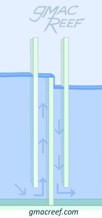
Configuration
The under-over-under pattern (as shown in diagram) is less commonly seen, but has a few benefits.
Installing Baffles in a Tank
There are many steps involved in selecting and preparing your glass baffles. This info has been split into it’s own post: Reef Tank Sumps: DIY and Construction
Things like measuring, cutting, glass thickness and prep work are shown. There are photos of a 40 breeder sump build with some helpful DIY techniques for working with glass and assembling the sump.
Refugiums and Sump Setups
Some people will install a refugium into their sump. While common, there are plenty of people that just do without them. The term itself has become a little generic. A “Fuge” often just refers to an area of the sump where there is lighting and stuff grows.
What is the Sump actually doing?
A repeated statement in reefkeeping information is that your refugium needs slow flow running through it. This is not true in all cases.
Some people will Tee off the return pump and divert a portion of the returned water to a “slow flow” chamber. Reducing flow like this is usually counter-productive if the refugium’s main job is to grow macroalgae.
Macroalgae grows the fastest with two things present. Good water flow (more oxygen) and lots of light in the proper spectrum. Reduced flow will just impede it’s growth.
So the question is, why bother Teeing the return line?
It is simple to just place the macroalgae in a sump chamber with consistent water height. Usually the macroalgae needs to be segregated or prevented from getting sucked into pumps. A plastic mesh divider or basket can be used in these cases.
Some refugiums are created as a habitat for microfauna and all the critters that live in the reef. These area are a true “refuge” and will usually have some kind of sandbed. Providing a safe place away from fish and predators will theoretically let them flourish and multiply. The ideal amount of flow for these types of refugium zones is a matter of debate and many people have tried to experiment with them but there isn’t really a consensus.
If you are building your first sump then you will probably get the most mileage out of trying your hand at growing macroalgae like Chaeto. A more complicated refugium setup can then be something you choose to experiment with or forgo altogether.
Basics of why to grow Macroalgae
By purposely encouraging its growth, Macroalgae can out-compete nuisance algae by consuming nutrients in the water column. Along with protein skimming, growing macroalgae is known as one form of “nutrient export.” The two most common types of macroalgae are Chaetomorpha (aka “Cheeto”) and Caulerpa.
More advanced designs
In the diagram at the top of this article, I show water moving from one end of the tank to the other. The water cascades, flowing from chamber to chamber like a waterfall. Illustrating the concept this way is simply done to make the concept easy to explain and show.
This design is generally a good practice. When the dividers span the whole width of the tank (front to back), the water passes over a longer weir. Having water pass over a longer weir allows for slower flow that is quieter.
Sometimes you want to go a little further with your design. In order to maximize what the sump can do, having each divider span the full width of the tank isn’t always the answer. More creative and intricate sump designs are possible. Rather than just having rectangular pieces of glass, you can create openings for water to pass through.
Cutting notched panels with the corner cut out allows for the sump to do a lot more with the minimum amount of dividers. For an example of this check out the Reef Tank Sump DIY Construction post or the 40 Breeder Sump Plans
Containing Spills and Being Proactive
Having a large sump with fairly high walls allows you to have a bit more piece of mind.
Equipment such as reactors have the potential to come apart and leak. The pump that drives them will continue to go, and can put water where you don’t want it.
Reactors may also have flimsy barbed fittings and tubing, especially on the cheaper models. If one of these fittings blows out, you want the reactor in a place where the water will only spill into the sump and not anywhere else.
The same also goes for things like a Skimmer’s Skimmate drainage Container. While common to be be located next to the sump, what is to happen if it overfills?
Anything with the potential to leak should ideally be located inside the walls of a sump or just above it. It can also be a good idea to install a water alarm in the cabinet.
There are many ways that a tank can potentially leak, which you should always be aware of. For this reason I have also written this post here: Common Causes of Flooding on Reef Tanks


Thanks for writing this great article. It is very useful an comprehensive.
If the first process in my sump is for water to drop in a mechanical sock then if using the herbie drain my main siphon line would actually have to be in the sock right?
Yes – I also went into more detail responding to your other comment on the Herbie Overflow page.
What about a 2 chamber design? Would I still need the 3 baffle setup between the 2 chambers, or if I space the skimmer/intake line far enough from the return, would simple eggcrate be good enough? (I’m building this in a 20 high for a 40 breeder DT).
The only necessary baffle is the 1st one. That will keep the skimmer in consistent water height. In a 20H tank you have limited space so I would put a single baffle in the center. If you try to create a 3-chamber design on a small tank it can cause a problem. This is because the return pump chamber will mostly likely be too small. If it can’t hold enough water, it will overfill when the pump is turned off. This will make the skimmer overflow, or in the worst case overflow the sump.
I recent bought a matured marine aquarium from someone and would like to know if I have set up the sump correctly as I’m not sure if it was take out of the cupboard during transport.
I have three chambers, baffles separate the first and second chamber, then I have the skimmer and then it seems a slight waterfall into the third chamber where the return pump is, should I turn the sump around so that the baffles are at the other end and should the skimmer be in the middle chamber or should it be in the first chamber with the inlet?
Thanks
Since the skimmer looks like it would fit, I would put it in the first chamber. This keeps it a little further away from the return pump and will give the microbubbles more time to dissipate.
Thank you, should I have anything in the middle chamber or maybe turn the sump around so that the baffles are at the return end?
Judging from the height of the baffles it looks like it was intended the other way around. I would only bother with turning it around if you have problems with microbubbles.
Hey, fantastic article, it really has helped me out with designing my sump. I’m planning on having a 2 chamber sump with a single baffle down the middle, in the first chamber I’m thinking of having a Tunze Comline 9004 Skimmer, as I have limited space. I will only have the return pump in the second chamber. Do you have any recommendations as to what else I can put in either chamber? Would Bio Balls be worth having? Thanks for your help!
Thanks! Glad it helped you. I would skip the bioballs, there are so many better options out there. I like using extra live rock and ceramic media like Siporax in my sumps. You can put the media it in a plastic basket so water can flow through it, and it can go in whatever chamber you like.
That’s great, i think I’ll go with the Siporax idea, it seems to be highly regarded. Thanks again!
Very informative article. I’m looking to build a internal sump like on the biocubes. I’m adding k-1 for amonia and nitrites. Then a refug for nitrates. Last a hob crp protein skimmer. My question is there a order these should be add in to make them more efficient.
Most of the time people use mechanical filtration like a sock or floss in the first chamber. Other than that, it doesn’t make too much difference what order you have chemical media, refugium, or skimmer sections.
I am building a new house and I have the opportunity to have a remote sump. The drain lines from the tank will be about 5′ at the bottom of the external overflow. The drain lines will then go down under the concrete slab and come out in the room with the remote sump. That room will be 4-6″ below the normal slab level where the tank sits. I am also planning on using 2″ high flex PVC tubing for my drain lines. By using this type of hose, I will not need any elbows. Normally sumps have the drain lines entering the top of the sump. Sump will most likely be 24″. In order to do this I would have to have my drain lines go up and over the edge of the sump. There would still be a 3′ difference between the starting point tank overflow and the end point sump. I was wondering instead of going over the top of the sump, could I just put a set of bulkheads in the side of the sump and have the water enter that way? So then the first chamber would fill from the bottom up vs top down.
I am a little unclear of what your setup looks like from the description, but I think I can still answer your question. The drain line outlets can take the form of bulkheads on the side of a tank. Their vertical placement would be important in relation to the water level if you are using a siphon-based method like the Herbie or Bean overflow. These methods require the siphon outlet to be submerged fully but not be underwater by more than 1″ in order to quickly purge air from the line.
Here is a picture of what I am looking to do. I am building a single level house. Floors will be a concrete slab. My builder says that my equipment room can be 12″ below the normal floor height of the rest of the house. The equipment room is 36′ in a straight line from tank1 which will be 225 gallons and 22′ from tank2 which will be 100 gallons. I am planning on using high flex PVC hose so that I will have a pipe or hose with no seams under the floor. In addition the hose will not require any elbows since it will bend as it goes under the floor. The drain hoses will enter the equipment room at 2″ above the floor height of that room. In order to keep from going over the top of the sump, I am going to install bulkhead fitting on the side of the sump and have the hoses go straight into the sump that way. Does that help?
There are a few potential problems here… Landmines really.
With the return line on this setup it will not fully drain the pipe when the pump shuts off. Are you in a cold climate? Running pipes under your concrete slab could result in freezing in winter.
The main problem I see is with the extent of the horizontal vs. vertical distance of the lines. This will create problems for a siphon based drain (Herbie or Bean setups). Horizontal runs create a place for air to get trapped in the line. In your case you’re looking at 20+ feet of them vs. only a few feet of vertical height.
The central piece of the Herbie and Bean overflow is based on designing a siphon to start reliably and quickly – which is hampered greatly with long horizontal runs.
In your case I would look into just having your sump in the stand right below the tank.
I just visited the house of a fellow reefer today. He has his tank setup with his equipment in an outside shed. Tank has been running for 5 years with no issues. Pipes leave house and then go down into the ground and come back up at the shed. Lines are horizontal with no drop He has no issues with getting air out of the pipes. I am in the Phoenix area. No issue with freezing.
Just trying to identify potential issues with what was described. There are far too many unknowns to do much more than that.
Hi great write ups. I’m doing my first sump and most I’ve seen though goes over > under on the last one. Am I going to have issues with sand in the refugium. And will it pass ok if I’m having a DSB
Thanks. I can’t say whether you’ll have any issues without seeing the setup.
Hello, my name is Xavi, i from barcelona, I´m preparing the design of my sump for a 100 Gallon reef aquarium. These are the designs and I would like to know what you think.
Thanks!!
https://uploads.disquscdn.com/images/117d099c44a62a43247c64b83568c57c2c1a38bfa79853c57b535f90aaeff301.jpg https://uploads.disquscdn.com/images/3be7c8df6de1b79ece1ad03583841a060e2307eed522c140f915f094e64df06f.jpg https://uploads.disquscdn.com/images/f2977340bd7c3f3bbad3ca0bb6078a5b8980b85cf41d9e36afb6e9400b54addb.jpg https://uploads.disquscdn.com/images/0e308913a93d5172c656fc898e8a0264e1526373b0a3ba52ed6a5521dc245a65.jpg https://uploads.disquscdn.com/images/2b6ccb690a906df875a973a99474ed0389ff7f3c73823b4c49f1b97fccc4f130.jpg https://uploads.disquscdn.com/images/5dfe9f059969312d8a5082651fe0da55261af2769c5412ff011e6aee21882505.jpg
I’m building a 22 gallon long sump for my 30 gallon display. Would it be OK do to the mechanical, biological and chemical in the middle compartment?
Thanks,
Glen
In my experience placing mechanical filtration in the first chamber makes the most sense. The sump stays cleaner of detritus that way. I use filter socks that the water passes through as soon as it drops into the sump. The biological and chemical media typically only affect a small amount of water at any given time so it doesn’t matter where those go in the sump.
I am trying to understand your bubble trap design. I understand you like the under/over/under. And recommend more than an 1″ space between the baffles. Let’s assume I go with 2″ between the baffles. You state:
“If you are passing water underneath a baffle, the panel should be raised off the glass the same distance. The height of the opening should be at least equal to the gap between individual baffles.”
Does that mean the baffles that are raised should be the same distance as the spacing between them? So raised 2″ off the bottom of sump?
Then the height of the opening, what do you mean here? Is that the height difference between the outside baffles and the middle baffle? So with 2″ spacing between baffles we should have the top of the middle baffle 2″ below the top of the outer baffles?
And if I go with the over/under/over, the spacing and height still applies. Just a difference in flow direction through bubble trap?
You are correct in that if the baffles are 2″ apart, then a center baffle would be raised 2″ off the bottom with an over/under/over configuration. This is just a best practice so that you don’t create a bottleneck where water rushes. By doing this, as water travels through the bubble trap, water will travel slowly and evenly. It depends on the turnover rate through the sump, but it’s a good general rule to follow.
If you go with over/under/over then yes – an even gap still applies. One thing to note with this setup however. You will want to make the 3rd panel (over) a 1/2″ shorter than the 1st (over) in order to keep the water level stable in the chamber that precedes the bubble trap.
Thanks for commenting, I will be adding some more info to clarify the concept.
Thank you for your information. I recently got back into the hobby and stumbled across this page. I have been having problems with my herbie and realized the drain pipe was to long into the sump. This info made it work flawlessly now and it creates suction within 15 seconds of a restart. Thanks for helping everyone out with this valuable info!!!
I have read almost all of your articles and learned new things or cemented a good understanding on different topics . Just wanted to say thanks !
If you enjoy writing those kind of articles you can go a bit more specific , for example combs designs , muffler designs for overflows etc.
Thank you for your comment. I actually started writing an article about overflow surface skimming, combs and weirs. I realized it isn’t the most interesting topic. Maybe I will publish it one of these days.
I watched too many videos, decided on a plan and started it, found yours and incorporated some of your info into my build. I don’t know how to send you a pic but, I have 5 baffles in a 20H. The skimmer will be in the space with the intake, then 3 baffles -over/under/over at 1″ spacing,-the first over is 10″ high, under is 1″ off tank floor and third one is 7 1/2″, 10 1/4″area length including baffles; next space 6 1/2″ – maybe refuge, maybe not; last 2 baffles- over/under and will be media area at 2″ overall, 1st at 6 3/4″, 2nd at 1″ from bottom like first under; last is return pump chamber at 5 1/2″ w, height of last baffles is 11″ including 1″ space underneath.
On a small sump like a 20 gallon you may want to just have less baffles in order to save space in the tank. On my 40 gal with a 13 gal sump I just have a single baffle in the center where water flows over into the return section/chamber. As long as the flow rate is lower (like below 300 GPH) then you will have minimal microbubbles to deal with. What you described sounds it will work. One thing to avoid is creating a really small volume in the return section because then your ATO will have to turn on and off more.