Returning water to the aquarium
While pumping water from the sump up to the display aquarium is fairly straightforward, there are a couple things to consider. Like other parts of plumbing an aquarium sump, there are many ways to accomplish the same thing.
The return line is part of the circulation system — and if you understand what it should do, you’ll realize just how few parts are required.
What are we trying to design here?
- a securely-mounted outlet that won’t budge or get knocked loose, but we can still disassemble it if needed.
- minimize the amount of water that flows back into the sump after the return pump is shut off.
How much water do I need to be moving through the system?
This is based on a few factors, and more details are presented here: What is the ideal Flow Rate of Turnover through the Sump?

Choosing Materials
Piping Material
The most common choice for plumbing is PVC – a time tested material that is both cheap and easy to find at hardware stores in various sizes. This guide is based mostly around the use of PVC.
Info about how to choose pipe material is presented on Plumbing a Reef Tank – What Pipe Material Should I use?
What size of Plumbing line and fittings should I use?
As for pipe diameter, your pump will dictate what you should go with, but it’s a good idea to go up a size. This will also allow the pump to not lose any head pressure from constricted pipe diameter. Many submersible pumps will have a 1/2″ outlet, and as a general rule most people don’t use anything smaller than 3/4″ plumbing for a return line.
It’s a good idea to just go ahead and use 1″ pipe for your return. It’s not much bigger in appearance, and you won’t lose any flow due to friction loss of a smaller diameter pipe.
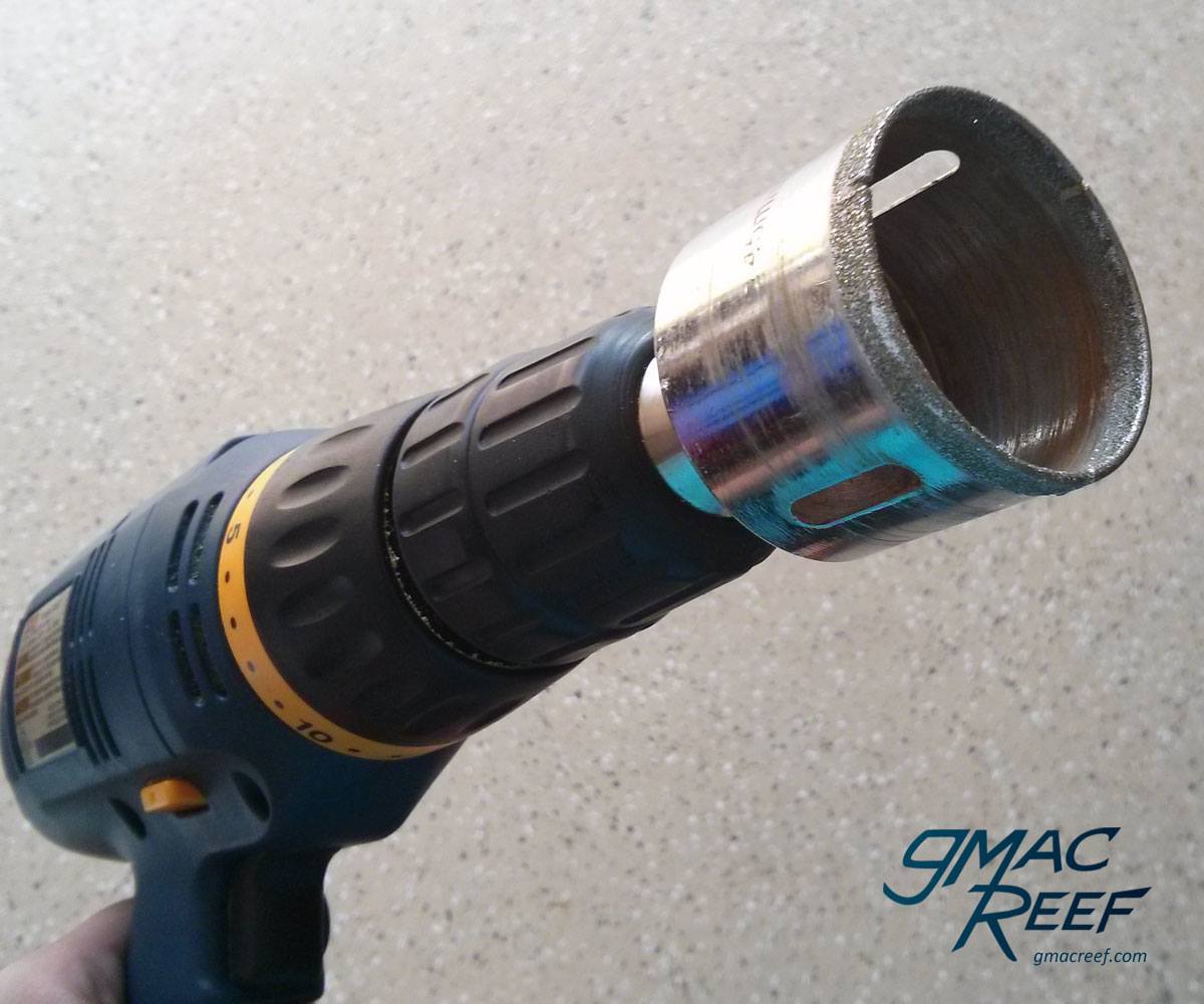
Connecting the Pump to the Return Line
 Return pumps need to be removed and cleaned out, usually every few months. If you are running a high-calcium stony-coral-type tank, then calcium deposits will form on the pump over time. This can eventually lead to it seizing up completely. As part of regular maintenance, most people take the pump out, remove the impeller, and soak it in a vinegar solution for a few hours. It can then be scrubbed with pipe cleaners or a stiff brush, and put back in.
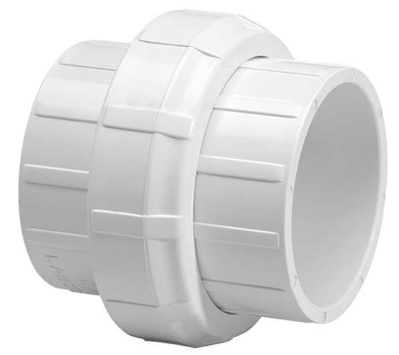
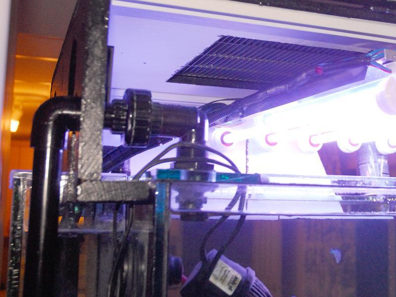
For this reason, you will want a union just above the pump to be able to disconnect the line.
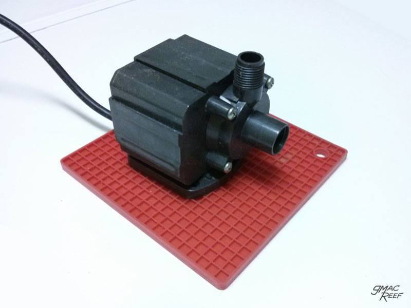
Dampening Vibrations from the Pump
Return pumps are also known to produce annoying vibration in your sump, and if you are running a large model, it can be quite loud. A silicone “Trivet” made for Hot cooking pots is a good addition under the pump. These are available from any store that sells kitchen supplies.
There is more info here: Selecting the Proper Return Pump for your Reef Tank
I did a video on this topic with the methods I use to make the pump run quiet: Silencing your noisy return pump and reef tank equipment
How the Overflow is Affected
Can I Tee off the return to divert some water elsewhere?
Some people will use a “T” fitting to direct a portion of the flow to a valve or series of valves. These extra outlets could do things like feed a reactor, refugium or skimmer.
If you are using a siphon based overflow method like a Herbie or Bean Animal drain, then the balanced flow of the siphon will be affected. Even small variations in flow will throw the balance off and it will need to be adjusted more frequently than is convenient.
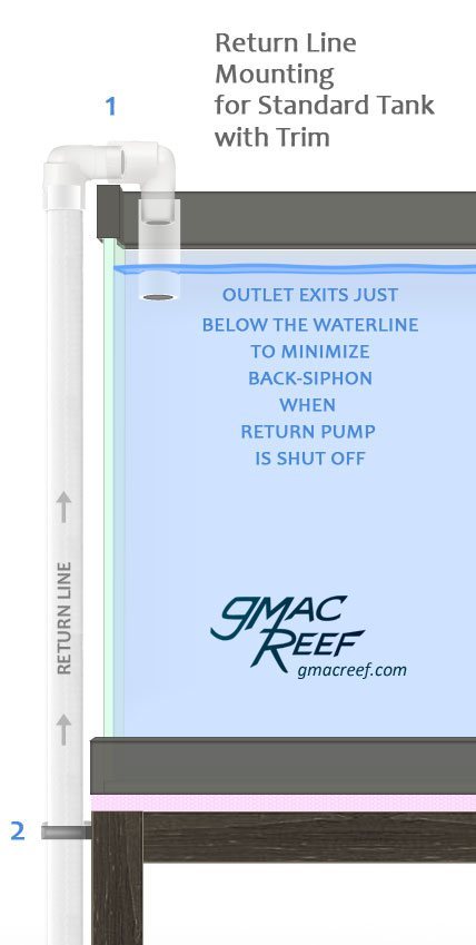
Mounting the Outlet to a Tank with Trim at the Top
Since this is where all the water from your tank passes through, it’s best not to cut corners with how you mount the return outlet to your tank and make sure it’s completely secure. Ideally you want it permanent, with the ability to disassemble it if needed. You want to make sure that the line can’t be knocked loose, which could result in a flood.
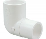
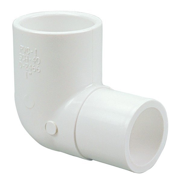
- Street 90 elbow fittings allow the pipe to point 180 degrees in a tight curve without extra pieces of PVC.
The parts that form the U shape should hang on the display tank and should fit snugly so it doesn’t move around.
In order to get a custom fit, you can play around with how far the pieces insert to one another, or even cut pieces to make them more compact. Make sure to glue the fittings when you’re done. - At the very least, you should mount the return line to the stand somehow using a PVC mounting bracket that screws in.
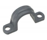 These are found in the electrical conduit section of hardware stores.
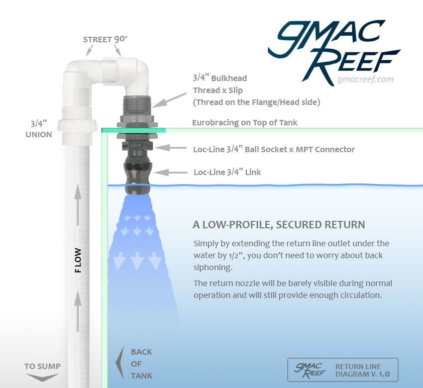
Mounting the Outlet to a Tank with Eurobracing
This design uses Euro-bracing along the back of the tank so it is probably only applicable If you have a custom Eurobraced Tank, the best possible method to mount the return line is through a hole in the top bracing. This eliminates all chance that the return can be bumped loose. One advantage is that the return nozzle is hardly noticeable in the tank at all. 3/4″ pipe is used in the example but if possible 1″ pipe should be used to lessen friction losses and maximize flow from the pump.
Should I install multiple return lines?
This is generally not necessary, and I will show you why.
If you inject a visible additive like an Alkalinity solution down at the intake of the return pump, you can observe just how quickly water mixes in a tank.
With adequate powerhead flow, all that water will mix together into a uniform haze in a few seconds with even low amounts of flow. This happens whether the the return is one outlet or many different ones. This is a good indication of why you need not worry about multiple outlets or placing an outlet as far away from the overflow as possible. Consider the following:
- Splitting the return can unnecessarily add to friction loss of the return system, lessening the output of the pump. In order to compensate for this, you would need multiple outlets – which are unsightly and provide no benefits
- Unless you have a 300+ gallon system or an 8′ long tank, there is no need to use more than a single return outlet
- A single return line is inconspicuous and easy to hide out of sight
Learn more about how “Flow” inside the tank differs from Return Rate:
Creating Flow in the Reef Tank
Back-Siphoning through the return line when power to the return pump stops
When the return pump stops, the filled-with-water return line will immediately reverse the direction of it’s flow via siphon action and start sucking in water from the main display. This is usually referred to as “Back Siphoning” because it is unintended.
The amount of water that drains during these few seconds can be minimized but not eliminated. The sump should have ample capacity to handle it.
Ways to avoid excess Back Siphoning
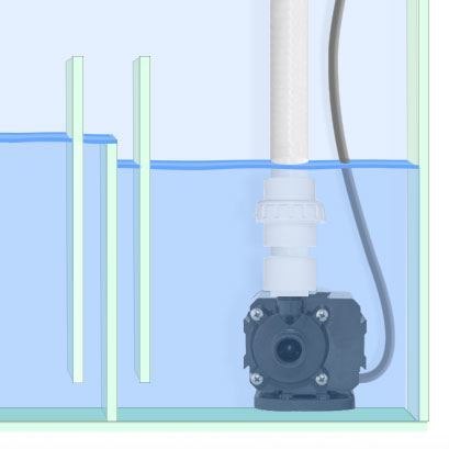
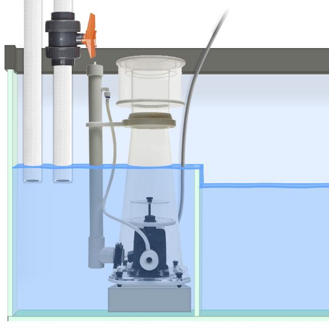
Install the return outlet nozzle just beneath the water surface
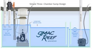
Simply by designing your outlet’s opening to be underwater by about 1/2″, you can eliminate excess back flow into the sump without the need for a check valve or any special fittings or methods. Other than sufficient sump capacity, this is all you need. This is the method explained in the diagram above.
Just for the sake of education, I will include the following info about some common mechanisms added to return lines. I don’t recommend either because of their likely probability of failure.
Other Methods – Click to Expand
Install a Check Valve
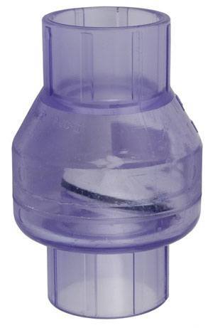 Some people opt to install a check valve somewhere in a vertical run of the line above the pump to limit back-siphoning. While very common, they are not necessary in every tank.
There are many types, some better than others. They all have the same shortfall – Stuff grows in them. Coco worms, snails, pieces of algae, anything. Once the seal is obstructed, they are useless.
You may enjoy months of trouble-free operation before this happens, but it will.
It is better to alter your sump design and minimize back siphoned water with the correct height of the drain inlets and return pump outlet. This is quite simple to do.
It goes back to the “Know thy self” philosophy.
“I’ll just clean it out” – yeah sure. The amount of people that clean the inside of their plumbing is about the same amount of people that clean the underside of their car.
Drilling a small “Anti-Siphon Hole”
– A small hole or two can be made in the pipe just under the surface of the water. As soon as this hole sucks in air, the siphon will be broken. These holes are usually made around 1/8″ in diameter — as anything smaller might not be able to reliably break the siphon. They are usually placed about 1/2″ beneath the surface of the water to avoid turbulence or create micro-bubbles.
Watch out – you should be aware that a small hole is very susceptible to getting clogged by debris or some kind of livestock in the tank. During normal operation at a positive pressure (water going out) this is unlikely to happen, however when flow stops, water will start to suck in through the hole, and it can tend to slurp up any surrounding algae or debris. It is also possible for the small hole to become completely covered by the growth of Coralline Algae. If the anti-siphon hole is clogged, the siphon continues until some air eventually enters the line from the main nozzle. If this is normally several inches beneath the surface, this can be a lot of water!
Have a backup plan – like sufficient sump capacity to account for this possibility.
The Spray factor – Under pressure, a small hole will also tend to blast out water, similar to a garden hose that springs a leak. This mini-jet of water can create noise, excess bubbles or put water where you don’t want it. For these reasons you might just want to avoid using an anti-siphon hole because of these potential problems.
I wasn’t serious and I don’t think he was either.
Trolling is a great fishing technique.
For the return piping how big to I want the pvc pipe that is going up, and do I need the same size for the streets? I do not plan to have a union.
It depends on the tank, but in most cases 1″ would be the minimum. In order to maximize the flow you get from your pump, you don’t want to go down in diameter from the pump’s connection. It’s a good rule of thumb to go up by 1/2″ with a bushing that connects into the main return line.
The street 90’s would be the same size as the main line. Also – I would recommend at least having one union just above the pump, extended by enough to keep it out of the water. You are going to need to clean the pump eventually.
So for example if I was to get a 3/4″ (Pump size) 2 foot long pvc pipe do I want to get a 3/4″ street? If that is correct wouldn’t the pipe be to big to fit?
In this example, yes. The street elbows are flared on one end to fit over existing 3/4″ pipe. The other end of the elbow is standard 3/4″ size which can go into another street elbow or connect to 3/4″ pipe with a coupling.
Ok, so I just set up my 90 gallon tank and I have had it set up before with no issues, so I know I just something stupid I am missing. I have a Y shaped line loc nozzle coming of my discharge pipe going in from the top of the tank. It has a little vent hole at the junction of the y that is above the water line but below the lip of the tank. It usually spits water out of the hole for a few seconds at start up then stops. Well now the vent hole has water spraying out constantly and wont stop. Any suggestions would greatly be appreciated
It sounds like you just need to adjust the fittings so the V junction (where the hole is) is pushed down a little bit. A siphon-break hole should be submerged when the return pump is running, and exposed to air when it is turned off. As the water drains from the display, the water line drops down to that point and it starts sucking air.
Having to worry about water spraying out of the siphon-break hole is one of the disadvantages of relying on that method to limit how much water drains to the sump.
I’m designing my system and plan on using 1″ pipe but loc-line doesn’t come in 1″ size. Suggestions?
I am less of a fan of loc-line now as I mostly think it’s unnecessary. Many people feel the need to use a 6″ or so length of it to “direct flow” but open themselves to risk. A return outlet using a length of loc-line can be bumped or moved unintentionally — which means your return outlet is pushed further under the surface. This could lead to more water back-siphoning from the display tank and overfilling the sump. I would leave it out of your design if possible.
GMAC I am planning on placing loc-line in my new tank, and purchased a Y splitter for it. I was planning on setting one really high close to the surface behind my aquascape, and one lower in the water column. When I lose power and it starts back siphoning, the first line to draw air would kill the siphon correct? I am pretty sure the answer is yes, but just making sure. I plan on installing a check valve as an added measure near the manifold.
Yes, as soon as air was drawn in from one of the inlets, the siphon would stop. I don’t like using long lengths of loc-line because of the back-siphoning issue. Also – splitting the return into many outlets is good in theory – but often only produces only a little extra flow in the tank.
I am venturing into my first sump and needed some advice on the return line pump. I plan to use a danner mag 18 which has a 3/4 mpt outlet with an inside diameter 1 1/2 based on my research. I want to use one inch PVC pipe for the return line into Display tank. What connections should I use to connect the pump to the one inch PVC pipe?
Here is how I do it, top to bottom:
1″ PVC to tank / return fittings
1″ union
1″ PVC (long enough to get union out of the water)
3/4″ fpt to 1″ slip reducer bushing
pump with 3/4″ mpt fitting
Thank you so very much. That helps me.
What is the significance of keeping the union out of the water?? Is there an issue with it being submerged?
Thank You!
No issue with it being submerged, but having it out of the water keeps things from growing on it and from it getting crusted up which can make it harder to loosen after several months. Less things to clean.
Thank You! Just wondered
Seems I made a foul, bleep and blunder…I finally got around to the pump and having the sump build…Now to where I think I messed up the mag 18 seems to be powerful for my setup as the water is leaving the section with pump quicker that it is being replaced. Any suggestions on how to correct. I guess options are ball valve and reduce flow or use a 3/4 pvc pipe or the last resort get a less powerful pump. That is me just thinking out loud but with your experience you may have a better solution.
You essentially have 2 options when plumbing for an oversized pump that is pushing too much water.
1. Use a valve to reduce the flow
2. Use a combination of a Tee and a valve to plumb it so you divert some flow back into the sump.
– I prefer the 2nd option because that way you can at least add some circulation to your sump.
Getting a new pump might ultimately be the best option, as changing the plumbing won’t help with noise. You may be able to offer a trade with someone in a local reef club or Facebook group to get something a bit smaller and better suited. Also – it’s never a bad idea to have a backup return pump on hand.
Thank you for your reply. Ok will probably look to replace the pump later this year. Will look at using the Tee with the valve. Any recommendations about where in the plumbing to install both. I am assuming the Tee will be just over the return pump area
Ok I went back and gave this some thought as I know I could not have made that big a mistake with the pump as I researched this thoroughly before I made the purchase. It was a simple issue of inflow v outflow – The standpipe in my overflow area was not draining to full capacity as the water level was too low. Once I ensured the water level was correct it started to work like a dream. Thank you for your help as this is my first time using a sump, doing the plumbing etc and your assistance aided me greatly.
I have a M1 Vectra return pump by eco tech marine. The outlet of the M1 pump is 1.25 inches pvc. I want to use this pump for my return and to feed my ATS. I want one pump to minimize noise in my family room and also my sump has limited space. It is a 50 gallon DT with with a ~15 gallon sump, herbie set up. The return connection to my DT is 3/4 inch. I am using vinyl tubing for the return to the DT. How would you plumb the M1? I am trying to minimize the restriction to flow and I want to vary the flow to the ATS; so I thought I would install a valve after the take off to the ATS (on the return line to the DT). That way If I restrict flow to the DT I would divert more flow to the ATS. I will install a union. Should the union be above the water when the pump is off or when it is on? When I transition from 1.25″ to 3/4″ is it better to make that transition close to the pump or higher after the union, (after the take off to the ATS)?
I greatly appreciate this awesome website and used it for my build. Thank you! Paul
Hi Paul – I would probably re-plumb the return line if possible with 1″ flex PVC. Vinyl tubing has the most drawbacks and potential for failure in reef tank plumbing. This post goes over pipe material: https://gmacreef.com/reef-tank-pipe-material/
The specs on the M1 pump seem a little oversized for your 50 gal application, but I realize it is a DC controllable model. From what I have read the British threads are hard to find fittings for to convert it over to US standard size. I am not sure why they went with a barbed fitting on the pump – almost all others have a threaded fitting.
In your case I would try to use a short length of silicone tubing coming from the pump. This short (under a foot) piece would then attach to to a barbed fitting that inserts into a slip x threaded coupling. from the coupling you can plumb to flex PVC up to the return outlet.
Using a short length of tubing to reduce the transfer of vibrations is a common technique. Doing this also safegaurds your tank against the pitfalls of barbed fittings – a pressure blowout where the fittings come apart. If you only use a short length of tubing – a leak should be contained in the sump. There is more info about this in the post I linked to above.
As for your other q’s – a union is usually best installed above the waterline (pump on or off) just for ease of adjustment. I will be updating my diagrams. Also I don’t think the location of a reducing bushing or other reducer makes much difference.
Glad you like the site – thanks for commenting.
I am starting to plumb my Sump, I have two bulkheads, supply and return. I have a Durso for the supply that I am plumbing a ball valve past the bulkhead, couple of 45’s to let the pvc not run horizzontal down to the sump. My pump has a 1/2″ fitting up to a 3/4″ ball valve, Backflow then up to a 90 deg leg – I will be sizing the pipe at this point with 1″ PVC running back to the bulkhead. Anything I need to look out for? I am totally new to the sump design. Sump will have a ATO, and a in Sump skimmer.
120 gallon reef.
ALSO – Is there a difference in normal plumbing supplies (HOME DEPOT) vs Reef Tank
A pic would help to identify any potential problems – it’s hard to explain this stuff in writing. As for plumbing supplies the PVC you get at Home Depot is the stuff you use on your reef tank. Check out this post I wrote about types of plumbing.
Dear GMAC REEF,
great website, really helpfull .
I am wanting to redo the plumbing on my 120 gal reef which has been running for a few years now.. The reason is the original plumbing is done with a 3/4 inch pvc which I now want to change to 1 inch for more flow through the sump..
I am using Fluval sp4 which is rated for 1800+ gallons so I am hoping 1 inch return will be more suitable ??
Also should the return and the drain both be of same size or I need to up the size of return ? I am also running 2 reactors via return pump.
Lastly, as I plan to redo the plumbing on existing reef how long should I let it cure before running the water through it ?
Thanks
Karan
The return line and drain don’t have to be sized the same. One is driven with a pump and the other is just using gravity so their sizes are not related in the system. 1″ pipe can move a lot more water than 3/4″ can. With PVC cement, you don’t have to wait more than a few minutes before running water through it, but try to do a rinse with freshwater if possible.
Starting a new project – I inherited a 125gal – 72″ long tank from a family member, who never had it up and running – so lots of fun ahead. the tank is manufactured with two rear overflows, each with two holes in the bottom – I plan to follow your advice on setting those up wit Herbie overflows, as its in a noise sensitive area, probably just using one and abandoning the other.
For return flow, I assume, there are two holes in the floor of the main tank, against the back wall, and just to the inside of each overflow column. I was considering either abandoning one, and running a stand pipe neat the top, with some adjustable discharge blades, or running two standpipes with discharge outlets, and maybe tee them together with a SCWD. I’m afraid the SCWD might mess with the Herbie set up too much.
Any suggestions on a dual return line arrangement? nice thing about a 72″ long stand, is the amount of room to work with underneath.
Appreciate any help, and thanks for all this valuable information in one place.
Personally I think I would cap off the two existing holes inside the tank (the ones not inside the overflows). Then I would run a single return line over the tank trim to position the outlet up high and pointing towards the middle of the tank. I wouldn’t bother with any SCWD or other nozzle contraptions. Having a single return line seems to maximize what your return pump can put out, giving the best bang for your buck as far as flow is concerned. It is also very simple. The only time I would really consider dual returns being necessary is if the length of the tank was 8ft or longer.
I have a tank that does not have overflow or return holes in it and I plan to cut them. Your diagram shows the return going over the lip and into the tank. Is this better than having a third hole (one overflow and one emergency overflow)?
I personally like having the return go over the top trim of the tank because it allows you to position the outlet high up. This limit’s back-siphoning without the use of a check valve. This is mostly preference but I wouldn’t say it’s better. If you are creating your own overflow then I would have 3 drains and use a Bean Animal style setup, while running the return separately.
I’m setting up a new 90 gal tank and have a question as to ideal flow direction through the sump. Which is preferable: to have the shortest piping from return pump to tank or from overflow to sump? Specifically, in my case the overflow and return plumbing is in the right rear corner of the tank. Would it be better to have the sump intake drain or the return pump right under the overflow? I’m trying to maximize overall flow (and efficiency as the pump is DC), but there may be other considerations I’m not aware of. Also, the tank comes with flexible tubing and threaded barb inserts to thread into the return and overflow drain; should I use this or use threaded pipe? Thanks.
A few more feet of lateral distance won’t add any measurable head pressure to the return pump, so flow from the outlet isn’t really affected by that.
Adding horizontal distance the pipes have to travel can negatively affect the drain setup. A siphon has a harder time purging air downwards if there is too much horizontal travel in the line. When designing your sump and system, sometimes it’s hard to avoid having a bit of horizontal run in your drain lines. If you can limit the distance then the siphon will start quicker.
For the fittings I would recommend, there is more info on this article Materials for Plumbing Reef Tanks. In short, If you have the chance to upgrade to PVC fittings, go ahead and do that if you want to maximize both return outlet flow and drain capacity.
This is great help. Thanks. Can I have a little advice as to why I would need a stop tap on my pipe work from my marine tank to the sump please other than for water changes?
The valve is used for creating a siphon – where you close off the flow a little bit. If you match the amount of water draining the tank to the amount being returned to it, you can create a quiet drain with the help of a siphon. The Herbie drain and BeanAnimal design both use this concept. Thanks for commenting.
I’m working on the pump return pluming for my 75g tank from a 20L sump. I purchased a Jebao DCT 6000, and the pump outlet is 1.25″ MPT. I planned on adapting this to a 1″ eshopps Flexihose to get me back up to the top of the aquarium. Now I’m looking for a 1″ return nozzle that either screws or glues to 1″ PVC…and am shocked to find nothing out there? Could I be missing something? I purposely upsized the pump to account for the head difference between the floor of the stand (where the pump is mounted) and the top edge of the tank, as well as the potential for upsizing the tank later on. I don’t want to restrict the flow at the end of the pipe with a 3/4″ nozzle if I can help it.
Suggestions?
You could just use a 1″ PVC fitting as a return outlet, but I would probably paint it black. I just got a new nozzle for my 150 gal tank which works really well. It’s called a Random Flow Generator and I have the 3/4″ model. It connects to Loc-Line. They have a 1″ model as well that connects directly to PVC. https://vividcreativeaquatics.com/shop/1in-random-flow-generator-rfg100/
Thanks for posting the link and for the support GMACReef! We really appreciate it.
I know this thread is from a few moths ago, but we have recently released a 1in modular hose and an RFG nozzle to go along with it
https://vividcreativeaquatics.com/shop/1in-random-flow-generator-with-1in-modular-hose-fitting-rfgs100ll/
This new nozzle comes with the 1in threaded NPT fitting making it perfect for 1in bulkheads and thread rerun pipes.
Your readers can find it directly on our website as well as on BRS
greetings,
return line from the sump at the tank???
choices…
1). straight down
2). 45 degree elbow
3). 90 degree elbow
return pump is a Sicce Syncra SDC 9.0
It doesn’t matter. On the return line, the fittings chosen makes such a small difference in the resulting pressure that it is hard to measure. BRS did a video on this: https://youtu.be/h-PG4a0rU60
my question is more of do I want the flow going down or do I want the flow across the surface?
Ahh – well in my case I have it pointing about 30deg down. I like having the return plumbed up as high as possible in the tank, to minimize back-siphoning. So I place it under the waterline just enough to prevent air being drawn in from a vortex, and giving some surface agitation.
I have a 7′ long 420 gallon tank that I’m setting up. The return pump is a reeflo snapper/dart gold hybrid with a 1.5″ outlet. I split that in to three 3/4″ return lines (one on each end and one in the middle) ran to 3/4″ bulkheads with loc-line inside. Was this not the way to go? Should I have ran 1.5″ all the way up, then reducing to 1″ bulkheads on the returns? Thanks.
I wouldn’t say what you did was bad. The location of where the pipes are reduced on the drain line doesn’t generally make much difference. For the most part I think that 2 returns are all that’s needed and that is only if you have a very long tank such as yours.
Thank you for your response. Much appreciated.
First of all, thanks for this excellent site. It did make me realize how dumb I have been with my plumbing. Now here is my dilemma. I’ve stepped down from a 300 gal to a 90 due to a blowout of the 300, long story on that one. Anyway due to a DIY stand, the DT sits much higher than a bought stand. This of course effects the head pressure of the pump and return flow to the DT. The DT has an overflow with 1″ return and 3/4 feed trough it. currently I have it plumbed as follow: Mag1800 pump >check valve > union > tubing > gate valve > pipe trough bulkhead > lock line > step down to 1/2″ lock line > flare nozzle to DT. I now realize the step down limit the pump output even more than I intended.
Since I do have a second mag1800 from my previous tank, I was thinking of adding it to the system to increase the flow. From my research on this I deducted the following set up:
Pump 1 > check valve > union> tubing > one side of wye (as I understand it, use of check valves on both pumps are imperative for dual pumps to one output)
Pump 2 > check valve > union> tubing > second side of wye
Wye > gate valve > pipe> 3/4 lock line, round nozzle to DT. ( removed the step down mistake from previous set up)
This should give me plenty return to DT. What are your taught on my planned set up?
If you have a Mag 18, then that pump is plenty capable of running your 90 gal on its own. It would be a good idea to redo the fittings going into the tank so the plumbing size isn’t reduced quite so much. At the very least upsize the 1/2″ section of Loc-line.
There doesn’t seem to be anything wrong with your proposed 2 pump setup, but again it seems like too much flow. I would also say that 1″ diameter pipe all the way to the tank would be necessary in that case.
Question about main drain pipe. The original pipe came with the system for the main drain is 25 mm in the overflow box and then below the tank, its 32mm.
This came from the manfacture this way. Do I need to change it or keep it as it is
Same for return, the return pipe below bulkhead is 32mm while above bulkhead is 16mm.
One last question is
I am planning to deploy a flow sensor which is 25 mm. What would be best way to do it. with the 32mm drain pipe below bulkhead.
Use a reducer after the bulkhead from 32 to 25 mm or just use the reducer before the flow sensor and then use adapter from 25 to 32 mm…. a bit confused how to put the flow sensor without affecting the drain and make it gurgling
As for the placement of a flow sensor – that should go on the return line, not the drains. It could interfere with the safe operation of a drain line too much. You are most likely trying to measure system turnover, so right above the return pump would be the best place to measure.
25mm is 1″, so without knowing what size tank you have you could potentially just leave it how it is, you can generally use 1″ lines for your main drain up to around 120 gallons in display tank size.
The flow of a pipe is determined by the narrowest part of it, so if part of the pipe (or a bulkhead) is a smaller diameter then there isn’t much point in upsizing it.
Oh man… I knew I wrote you once but for the life of me I could not get in which article i posted and I searched for every until i came across this article by chance. I posted another question in another age but can not find it but happy I found at least this one 🙂
First thanks for the reply . Your website really is helpful and informative like no other.
So my tank is 360 liter with sump 120 L . I am planning to go with Triton method so I would need about 7-10 time turnover. I think it make snese as you mentioned that 5-7x would be good enough as power heads will help also moving the water in the DT.
I found that my bulkhead is 1″ * 3/4″ where 25mm pipes are included for overflow box and 32mm pipes for sump area.
If aiming for 10x turnover, would the 25mm bottleneck be enough for the turnover 10x?
The bulkhead hole is 36mm dia so I found a 32mm bulkhead (Hole required 34-39mm) from both sides. Thought if I need to replace the bulkhead to have 32mm from both sides to get close to the desired turnover. Would this work?
How about the noise if I change to 32mm pipes using herbi method. Some told me the system will be more noisy and louder when changing to bigger pipes.
Once again. Thanks for the wonderful site.
Hey bud.i really like what you’ve done here.thanks for all the info.
I am currently starting the plumbing on my 75 gallon tank with a corner Herbie overflow.both bulkheads are 1 inch for the drain lines which will be going into a trigger systems ruby 30 sump.one of the drain lines is a straight run down to the sump and the other drain line mite need a 45 or 2 to get it into the sump.i just wanted to know which one I should use for the emergency drain.the one with the straight run into the sump or the one that has the 45?
I also wanted to know if I can put a T on the return outlet and put a cepex ball valve to control the flow into my refugium?
And last question.would you use a cepex true union ball valve on the return and the drain or a gate valve?
Sorry for all the questions lol
In your case it most likely doesn’t matter what pipe you choose for the E-drain vs the siphon pipe. 45’s or even 90’s are fine to use, you just generally want to avoid long horizontal runs for the siphon drain line. Even in that case, you will generally be fine with a horizontal run of under 3 feet in length.
You can use a Cepex ball valve. These are high quality valves with a smooth open-close action. They can be finely adjusted. Some people say gate valves are mandatory, but high quality True-Union Ball Valves are just as good in my opinion for these applications.
After hours of research on how to design my RO production, salt-water-mixing station, and salt-water pipeline to fill the display tank–I finally found this thread on your outstanding website! Thank you! I have a Red Sea Max (RSM) 130D (34 gallons) and I’m not running a sump or anything fancy, so I don’t need huge amounts of RO and salt water stored. I had planned to buy two 20-gallon water storage tanks and stack the tank for RO above the tank for salt water, but I have enough room not to stack the tanks and go side by side if needed. Each tank is only 31″ tall, so stacking makes sense for comfortable work height and saving floor space. The tanks have a 1/2″ outlet/bulkhead. I don’t want an overpowered pump because of function, energy savings, and my storage tanks are only 20 gallons so I’m not worried about saving a few seconds filling them up faster.
First, should I buy tanks that have a larger outlet (of 3/4″ or 1″), because that would necessitate going up in tank size and I’m trying to right-size this thing?
Second, which pump should I buy if I stick with my plan on the 20-gallon, 1/2″-outlet tanks I want to buy?
The factors in which pump to buy: 1) the inlet pipe for filling the top RO tank will be about 5.5 to 6 feet above the ground (where the pump will likely sit), 2) I want to use the pump to fill my display tank with salt water and the top of the tank is about 40 feet of flex pipe away and about 6-7 feet higher than the pump location in the garage. I had planned to buy the Iwaki MD-15RLT because I thought it was the best quality pump for the power (head) that I think I need, and it has a 1/2-inch inlet and outlet to match the tanks’ 1/2-inch outlet.
Is that a good choice in pump for the reasons I mentioned, or should I go for a stronger pump with a 3/4″ inlet and outlet?
If you see no reason why I shouldn’t go with the 20-gallon tanks and Iwaki pump I have planned, should I increase the PVC piping to 3/4″ with a bushing immediately after the tanks’ factory-threaded 1/2-inch outlet, and immediately after the pump’s 1/2-inch outlet, or will I be fine with the 1/2″ PVC piping?
Answers to these four questions would be most appreciated and any other advice and tips will be gratefully received.
On my 320 gallon reef, I ran a single 1 1/2″ return pipe up and over the back of the aquarium. My aquarium water height is around 27″ including an inch or so of sand. My problem is that the return washes away all of the sand underneath in the back corner. Is there anything to add to the plumbing outlet to soften the force of the water to prevent it from washing away my sand?
It sounds like a problem that could be fixed with changing the outlet nozzle. If the outlet is being reduced from the 1.5″ a fair bit, you will get more of a narrow jet of flow in the tank. I would make sure the nozzle is aimed into the middle of the tank in an open area where the flow can churn up the most water. You also might want to try a Randow Flow Generator from Vivid Creative Aquatics. They are good at breaking up the flow from a single stream.
I have a couple of questions. Im planning on buying a 250 gallon aquarium that comes pre drilled with a 1.5″ inch bulkhead as a drain and two 3/4 inch return bulkheads. These bulkheads are located on the back side wall of the aquarium approximately 2 inches below the trim of the tank. My questions are: will this setup be enough to get the adequate turnover rate that I would like (7x-10×) throughout the system? Or would I need to drill another hole to drain more water into the sump. The current return pump I plan to buy is rated for 2400 gph flow, would I need to upsize my returns as well?
From what you have described, a single 1.5″ bulkhead won’t be sufficient and you will probably have to drill more holes in your 250 gallon tank. I would look into one of the larger overflow setups that can have 3 individual 1.5″ drains such as a Synergy Shadow Overflow.
You should be good with 1″ returns.
I wanted to replace the 1/2″ loc-line coming from my return line into my tank. I attempted to attach my new loc-line to the 1/2″ ball socket x mpt connector, but can’t connect them. Is there a special tool or trick? Help!
Yes, there is a special tool you can use for Loc-line that looks like a pair of pliers. It can be really hard to join the pieces. I don’t have the tool but sometimes I will use my bench vice. Also – there can be off-branded fittings that are made to work with Loc-line but might not be a perfect fit, so it might result in a fit that is too loose. Usually this can be fixed with a small piece of tape on the male side. For really tight fittings a bit of heat from a heat gun can help.
Hi GMAC,
Firstly, thank you for this site and its information. Its been immensely helpful in setting up my 150 freshwater tank. Ive been running it for 3 years now and have continually noticed that as the water level in my sump drops so does the water level in my overflow, to the point that it will reach the siphon. Ive double check my plumbing and the flow going through the valve on the main drain without seeing anything that I can determine is the problem there. My one thought is that as the water level changes on my return pump that it changes the pressure it pushing out. The water level is always steady when I keep the sump at the max Ive determined, but as it evaporates the overflow drops. Im running a Jebao DCP Sine Wave Water Return Pump. Have you seen this happen before? Thank you!
Yes, I have seen that before. The pump pushes slightly more water when it is easier for it to do so. When the water is deeper, such as when there is a larger volume “pushing down” on it. This will create small variances in the rate of turnover through your return, affecting how much water the siphon is getting.
Having an Auto Top Off would fix this issue. An ATO is practically a must on a Saltwater tank. For Freshwater, it’s still nice to have.
I just bought a second hand 90 gallon tank with a internal overflow box. Inside box it has a 1 inch hole and a 3/4 inch hole. I’m planning on using the Herbie method. Question is should I use the 3/4 for the main drain and the 1 inch for the emergency drain. If so then should I use 3/4 from the pump for the return line.
Another option is use the 1 inch hole for main drain and return line. Then use a 3/4 to 1 inch adapter at the bulk head with 1 inch pipe down to sump. Will this create a bottle neck?
Any suggestions would be great. Thank you.
For the Herbie setup, if you have two pipes available, you would use the larger of the two as the Emergency drain. So the 1″ E-drain and 3/4″ siphon line would be plumbed down to the sump.
Not sure about the 2nd half of your question. If you only have 2 pipes in the overflow box then the return will have to be plumbed separately. As for the return line size I would go with a 1″ return line on a 90 gal just to maximize the pump potential output.
I’m gonna have to do a really silly setup because of the way my table is made.
From my (planned) Sicce Syncra (2.0), which uses a 3/4″ ID barbed fitting for the tube, I’ll have to do at least partially soft plumbing. However, I really like Loc-Line and would like to do the dual nozzle setup, so I’m going to have to somehow connect a Loc-Line. These are the questions I have:
– What connections would I have to use to *directly connect* 3/4″ ID – 1″ OD tubing to PVC, so that I could then connect the NPT connectors, which would allow me to use Loc-Line tubing? – What PVC size am I looking for (Sch40)?
– I plan on using 3/4″ Loc-Line if possible, but is that the right size for what I need? I have a 20 gallon (standard) tank, and my overflow will be pulling ~300 GPH along with the return pump pulling roughly the same (slightly more).
3/4″ loc line will work for you, you could even use 1/2″ with that flow rate. You can use a dual nozzle setup if you want with a “Y” splitter but a single outlet will work fine. The threaded 3/4″ Loc-line fitting that has threads on one end and the ball-type end on the other should thread into a standard 3/4″ PVC Slip x FPT fitting to connect to the rest of the return plumbing.
Hello! I am setting up a 36 gallon bow front aquarium and want to ask you your opinion on the placement of the return outlet.
I normally put the overflow in the center and the return to the far right corner. I’ve read where people have put the return in the very center and put the overflow next to it. Are there any benefits to this layout? Is it better for flow to have it hitting the center of the bow front and going out both ways? Or is it just a matter of preference? Thanks in advance!
It’s mostly a matter of preference of where you put the return outlet and where you want to direct the flow. On a very large or long tank it matters more. On a small tank like a 36 gal the placement of the return isn’t going to change much as long as there is adequate flow in the tank.
Let me start out by thanking you for these incredibly informative webpages!
I’ve been an aquarist for many years, but I’ve as yet no experience with overflows, sumps and the plumbing associated with them. That’s about to change, though, as I just purchased a new 6-foot, 180-gallon aquarium with back corner overflows and associated predrilled bottom holes, and I plan to filter the aquarium using a 60-gallon breeder tank that I’m going to DIY into a multi-compartment sump in the stand’s cabinet. It will be a freshwater setup.
I live a relatively solitary, rural life with no mentor or even just knowledgeable friends around who can instruct me on this stuff. I’ve been reading everything I can find to get myself up to speed, and I must say that your webpages are the best material I’ve found – and I really appreciate your efforts on all our behalf! I only just discovered that your Q&A section is still active, too, and I’m even more thankful for that!
Because I’ve some questions for which I’ve been unable to find answers, of course… ;^/
Per the aquarium’s manufacturer, the predrilled holes are meant to accommodate one 1” drain and one 3/4″ return (those being the bulkhead sizes rather than hole dimensions, of course) in each overflow, so 2 drains and 2 returns in total. But based on my reading and rumination, I thought I would configure things differently:
• using both holes meant for the 3/4” returns instead for siphon drains with the standpipes’ inlets 6″ below normal water level, controlled by gate valves en route to the sump,
• using one of the holes meant for a 1” drain for a Herbie Overflow drain with the standpipe just a trickle below normal water level, no valve, and
• using the other hole meant for a 1″ drain instead for a single return, served by a DC return pump (2-130W, finely adjustable) in the sump’s last compartment and protected from backflow by a check valve.
*** Is there any reason I shouldn’t do this?
As I said, the manufacturer predrilled holes to accommodate particularly sized bulkheads (1” and 3/4”). But I’ve read varying things on whether I should just go with the same sized PVC piping or whether I should use larger piping over as much of a line as is practical (e.g. using 1″ pipe for a 3/4″ bulkhead, I suppose by using a reducing coupler to connect it to a short piece of 3/4” pipe connected to the bulkhead?).
*** Is there really any advantage in using larger piping for some portion of the drains, the return or all of it? Isn’t the flow rate in a line capped by the line’s narrowest constriction – i.e. in my case the size of the bulkheads, which I can’t change – in any event?
As for the return, I‘ve been thinking I would plumb it over the top of the overflow box to a spraybar placed just below normal water level at the back center of the tank, aimed either directly downward or more likely at something like a 45-degree downward and forward angle. Or maybe split the return to 2 nozzles aimed similarly. Or …? (I read with interest your recommendation of a VCA Random Flow Generator, so I’m thinking about those, too.) The fish I keep don’t require strong currents in the tank, so mainly I just want the outflow to be relatively unobtrusive, provide decent circulation, and maybe also help blow poo toward the front of the tank so that I can more easily vacuum it out. I figure I can always use auxiliary powerheads if I want to direct more flow anywhere in particular.
*** What would you recommend that I do for the return’s outflow?
Finally, I’d like to ask you about water levels…
In the sump, I’m fine with maintaining whatever water levels are appropriate to the various compartments and also leaving unfilled capacity to handle a possible emergency. If you have additional thoughts on sump water levels I would welcome them, though.
But with respect to the main tank, I’ve always strongly preferred that the water level be hidden by the aquarium’s top trim if possible (I’m using glass lids, no canopy), especially because I have very hard water and the waterline quickly becomes unsightly. The thing is, the bottom of the tank’s trim overlaps with the very tops of the overflow boxes by only 1/4″, if that, and the top of the 1 1/2″ vertical slots that serve as strainers for the overflow boxes (they’re not teeth that are open along the top) start another 1/4″ below that. So if I want the water to be strained as it enters the overflow boxes – and I do, naturally – then I’m already going to have the water level at least a bit below the trim. The overflow boxes came with adjustable weirs to raise the effective bottom of the strainer slots as desired, but they weren’t accompanied by any advice on how best to set them. I understand that I want the water to pour through those slots and fall only around 1/2” or so to the height of the Herbie Overflow standpipe (with the siphon drains’ valves and the return pump set to provide no more than a trickle down that pipe), but I also read in your webpages that:
“The distance between the E-drain inlet and the top edge of the tank needs to be a few inches to aid with capacity. This is needed in the event of a main siphon line blockage.
If this happens, the E-drain will possibly need to go full-siphon as well. If the standpipe places the inlet too high up, a siphon may not be able to engage on the E-drain if it has to before the tank’s water level swells to the top edge of the tank and starts to overflow it.”
I understand what you’re saying in general, but I’m having a difficult time translating it to my setup specifically. Especially so because I will have 2 rather than 1 regular siphon drains if I go with the arrangement I described above, and presumably it would be quite unlikely that both would block at the same time, so the Herbie Overflow’s job will be to help handle drainage if 1 siphon drain becomes incapacitated rather than to take over drainage completely for both of them.
*** Given that, what do you think I can reasonably get away with for the distance between the E-drain inlet and the maximum possible fill line of the tank? (There is only 3/4″ between that absolute maximum and the tops of the overflow boxes.) If you still think it should be at least a few inches, can you narrow that down a bit more for me? I know that one person’s “few” can be another person’s “several”… ;^/
I’m sorry to have gone so long (hopefully it’s all understandable!), and to ask so much of you. I could really use your help, though, and I would appreciate it more than I can say. And I promise to pay your kindness forward whenever I have the opportunity!
Hi – if you have your heart set on not having a return line that goes up and over the lip of the tank, I would direct you to Herbie for Dual Overflows. Option 3 would be closest to what you are describing. Using all 4 pipes as drains is a better way to do it though.
It sounds like you understand the pipe diameter part of it, always use the larger of the two bulkheads (1″ in your case) as the emergency drain and the smaller one as the siphon valve drain. Also yes – there is not much benefit to using larger pipe size for a run of pipe if it ultimately must squeeze through a narrow opening like a bulkhead. The narrowest part of it determines the flow rate.
For the return, the only experience I have with spray bars is when I had a canister filter. If your goal is to move fish waste around I would skip the spray bar and use an outlet to boost flow in the tank.
As for water levels in your particular tank concerning the weir teeth, I’d say there are just too many factors and it would be hard to give you advice without seeing the setup. So for this type of thing just experimenting yourself would be the best, such as setting the tank up in a garage or outdoors to test the setup and see how adjusting the weir height affects things.
Lastly – concerning the distance between the E-drain inlet and the top of the tank, I think when I wrote that it was just to get people to think about that generally.
If someone had a super strong pump and no room above the E-drain inlet, it could be possible to have water spill over the top of the tank. Unlikely but not impossible, just something to be aware of.